WeirdCube 3D Printer - Devlog 4 - The Core XY Kinematics
This WeirdCube 3D Printer article is about the design, assembly and test of the Core XY motion system.
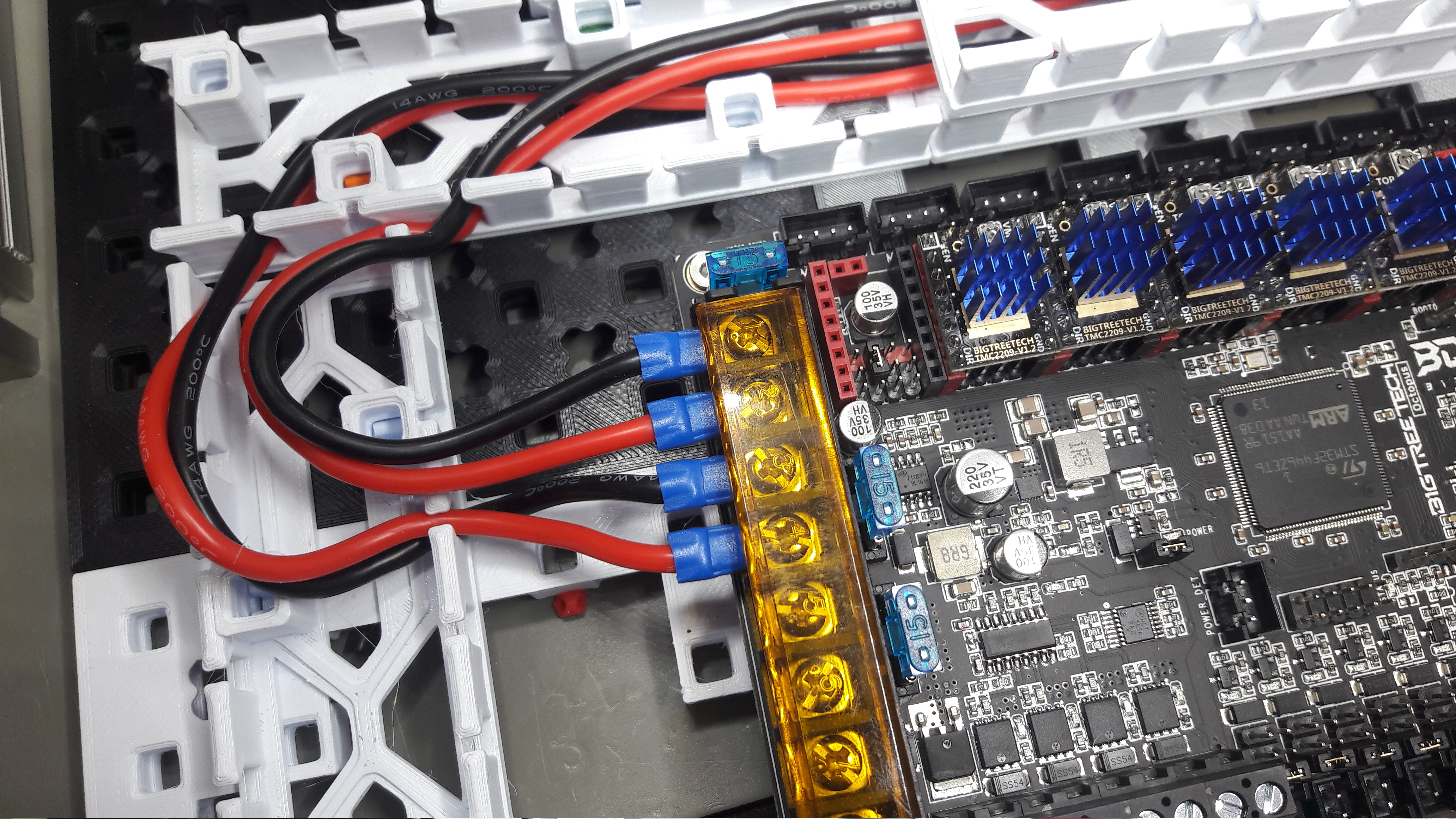
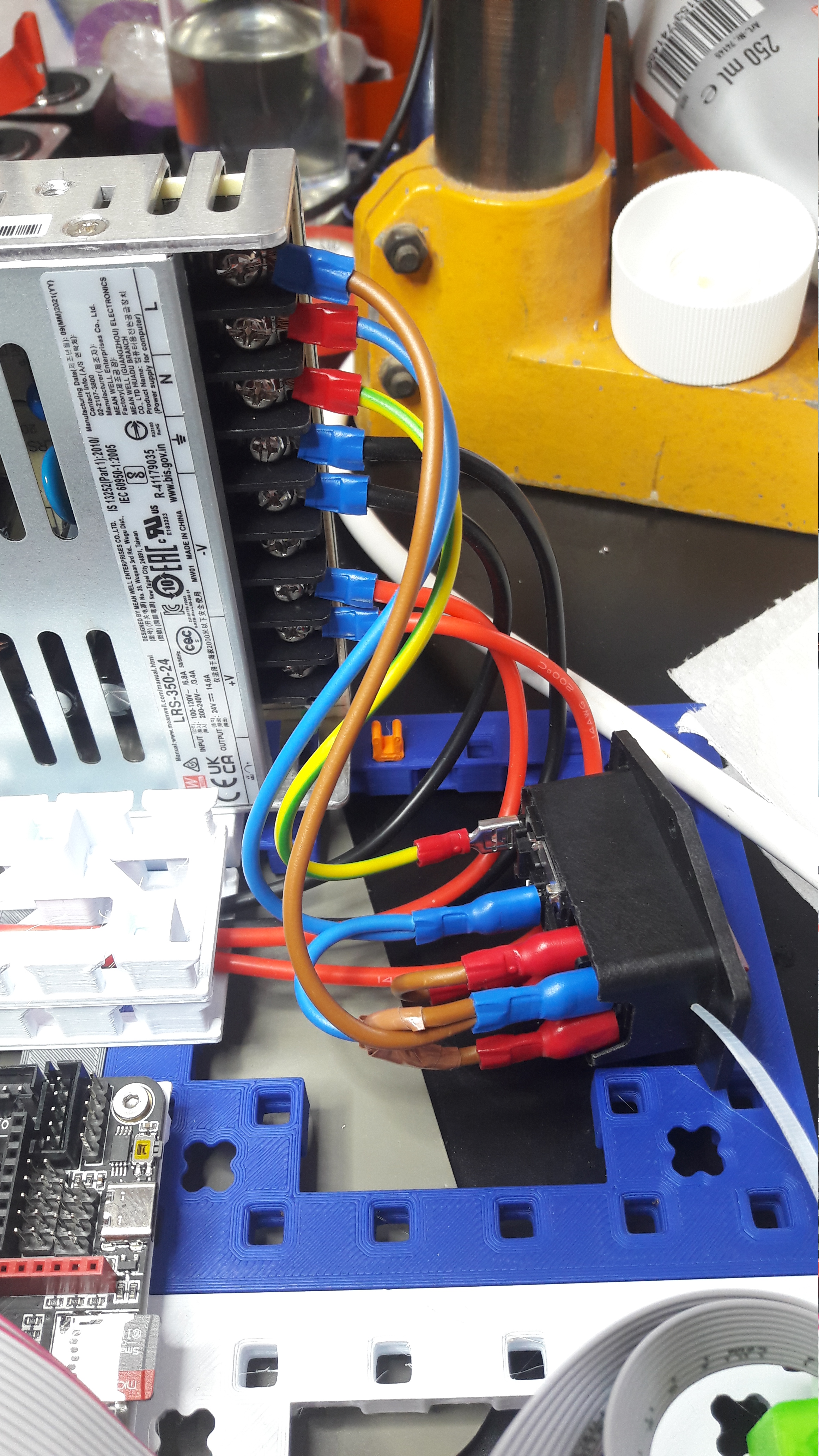
Lets start off the article with a bit of electronics work. I ordered a few cable shoes to replace the ferrules for an even more secure assembly.
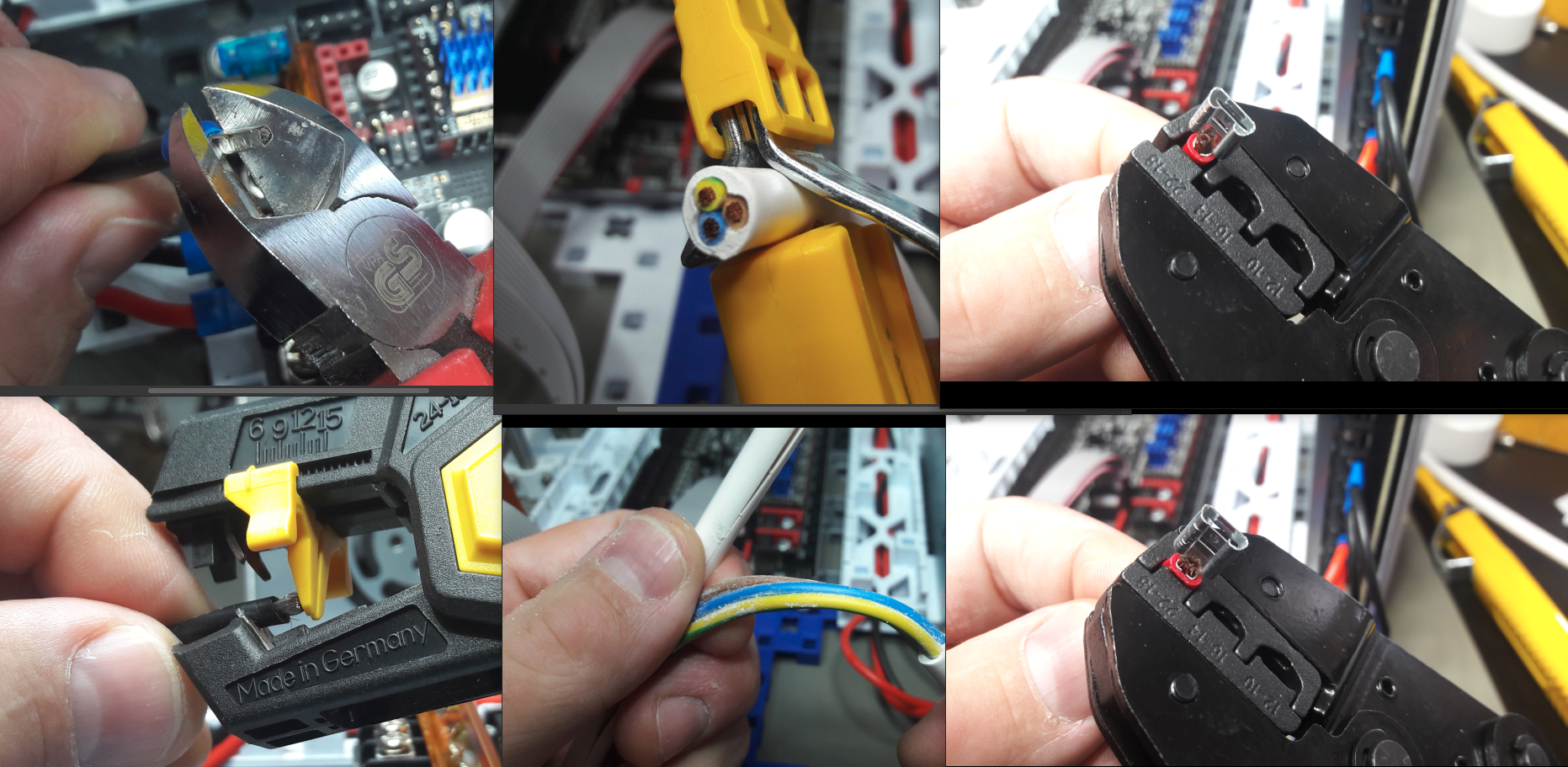
I also ordered a power plug socket with switch. Please don't look too closely, I got the wiring wrong in these pictures, but I found the bug once I checked it.
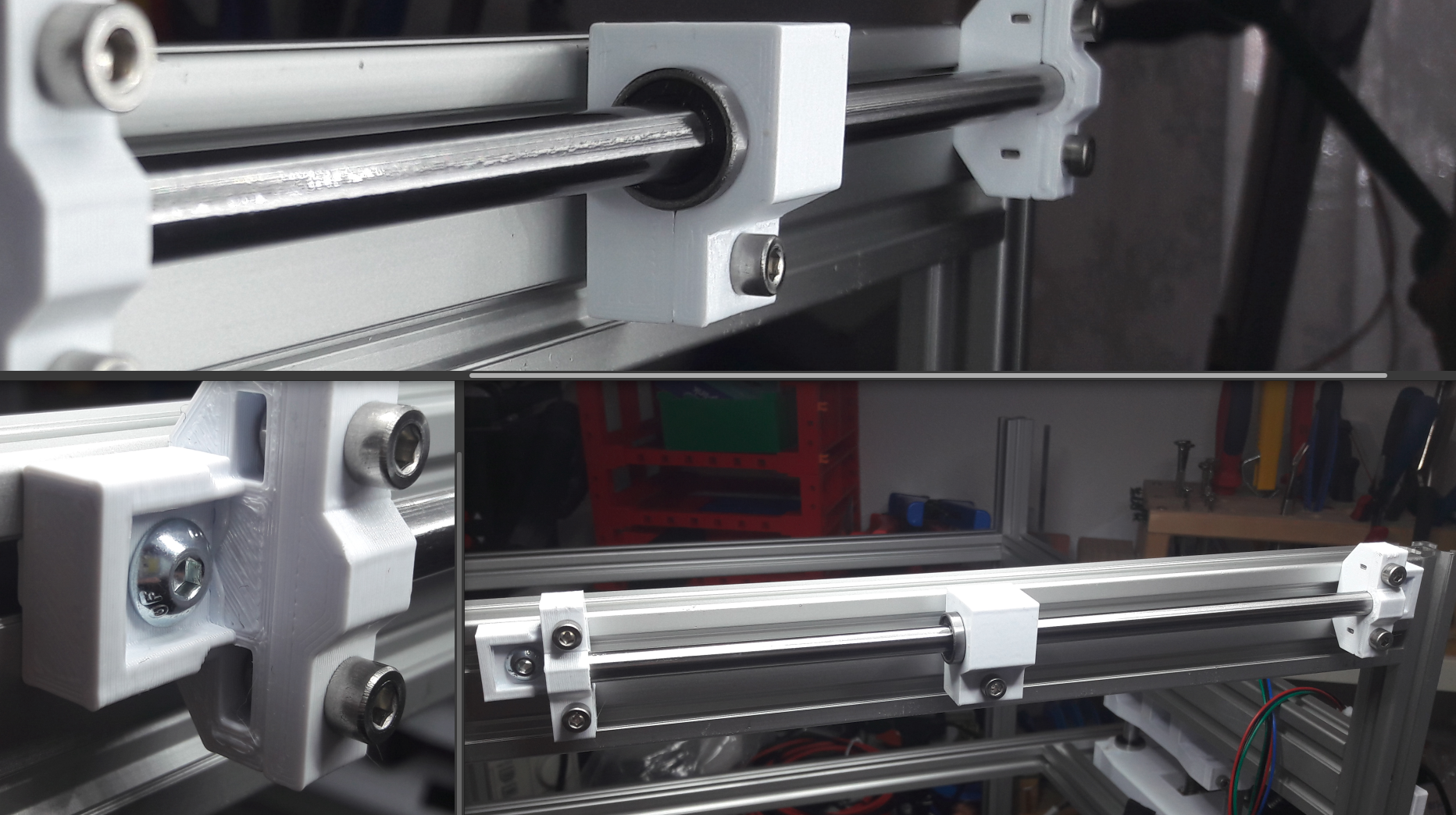
X/Y Precision Rods
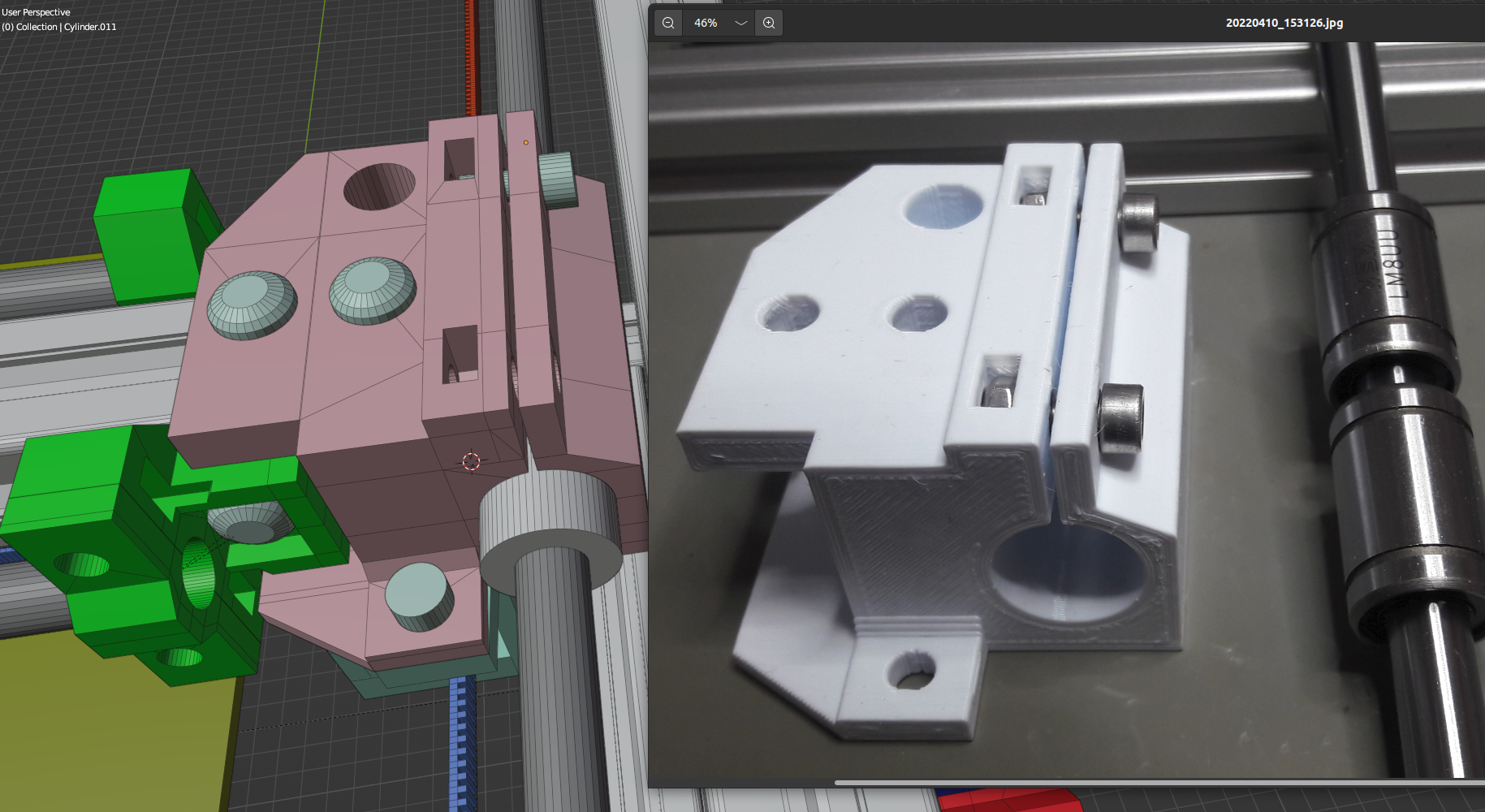
I started by prototyping holders for the rods and something to grab onto the bearings.
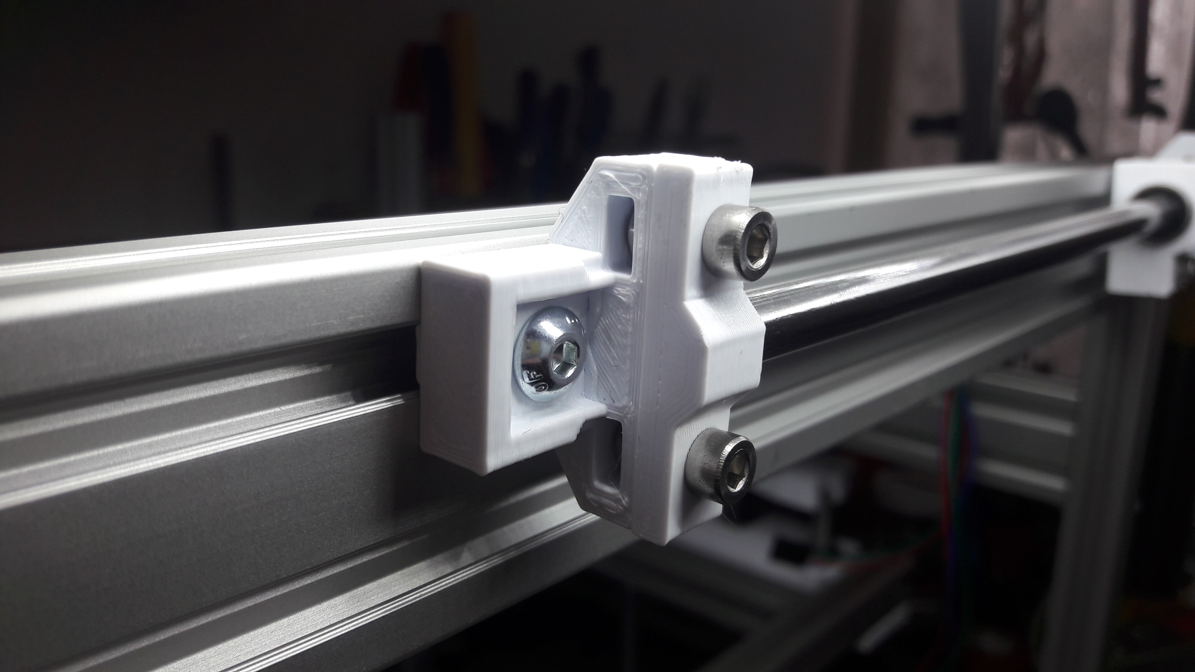
For space reasons I decided to have only one screw for fixing the bearings inside the part. This reduces the necessary forces for precisely mounting the part to the LM8UU bearing.

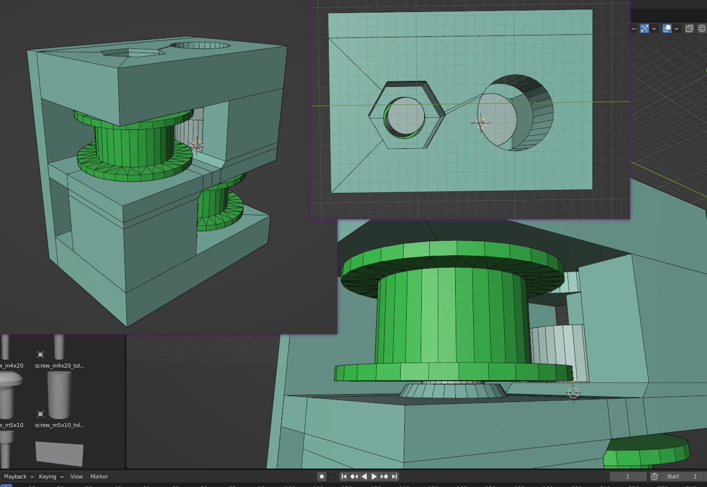
Core XY Pulley Holders
Next up was the task of finding a design for the pulleys. I only have a limited set of screws at my disposal. So all I had that fitted the pulleys with a 5mm bore in the middle were my M5 screws, of which I had M5x10 and M5x20. So I had to design something that holds M5x20 screws. The first prototype was the following, which I later stabilized a bit due to too easy cracking.
I designed it that way, that I could use this holder design for the X gantry as well as for the pulleys in the back of the printer.
I printed it on it's side for the beginning. Later I decided to print it laying on it's back. Either way would be fine after all.
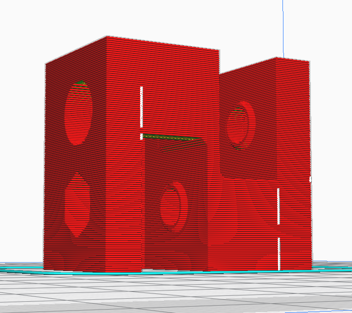
After printing I tested the pulley holders, whether it's fitting the belts properly and could be assembled.
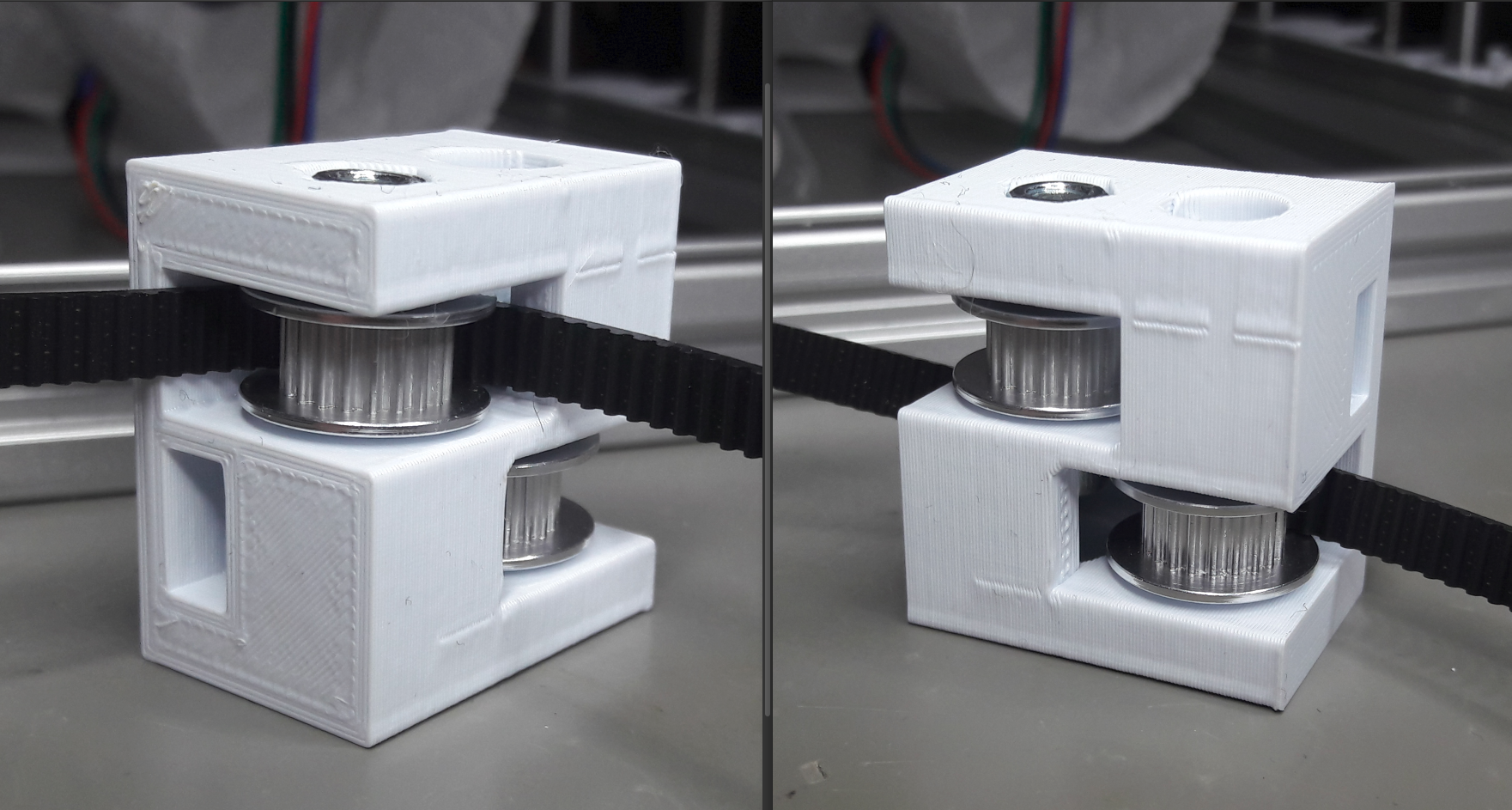
Unfortunately it turned out, that the M5 screws can be easily overtightened and I got a crack too easy. The following picture shows the problem after over tightening the M5 screws on purpose.
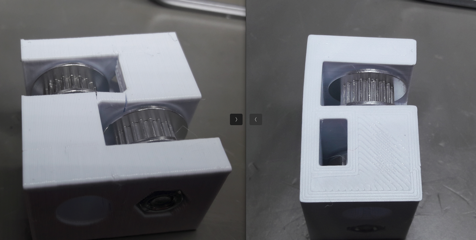
For more stability I added pillars on the front of the pulleys too, to get rid of the U shape.
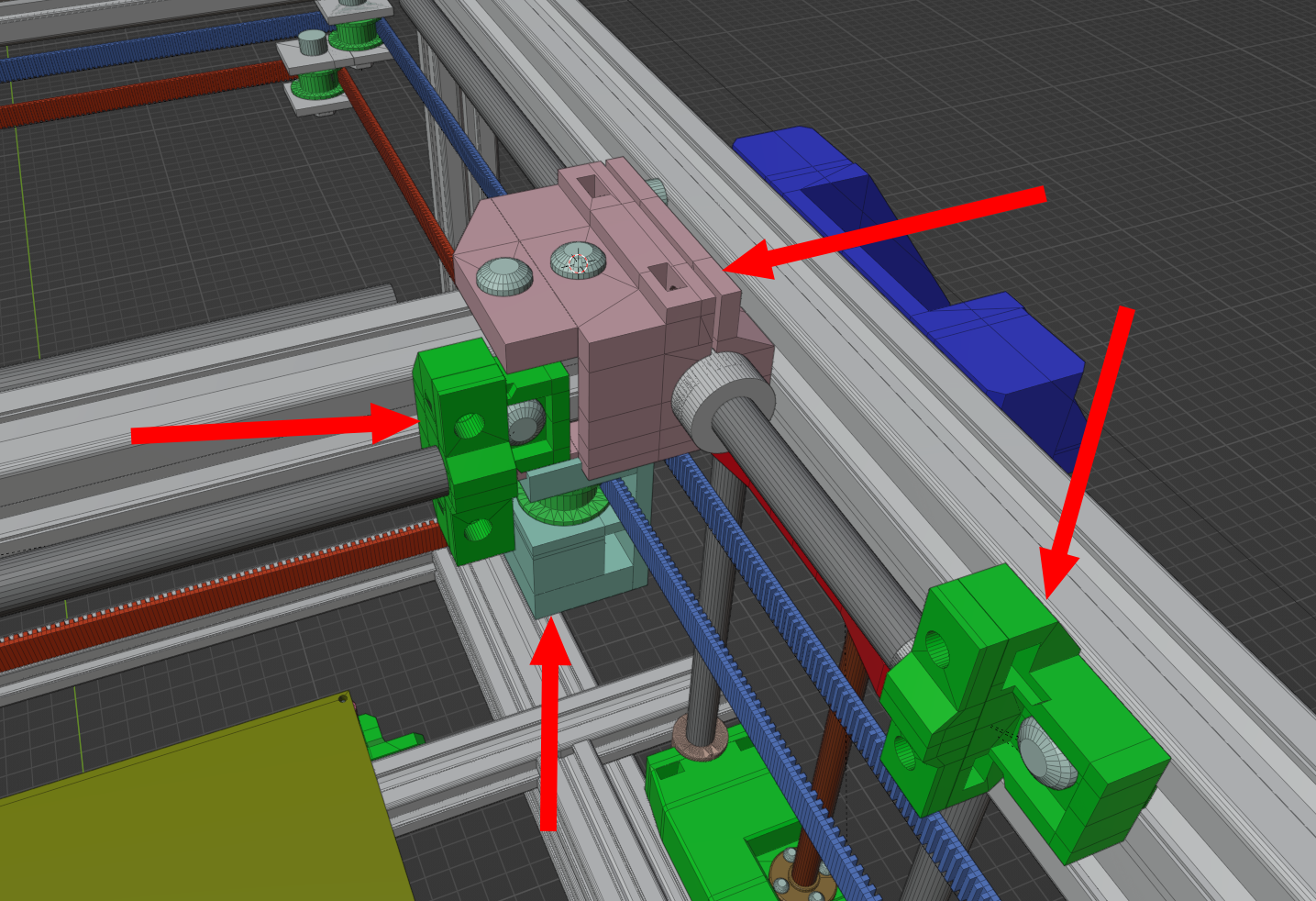
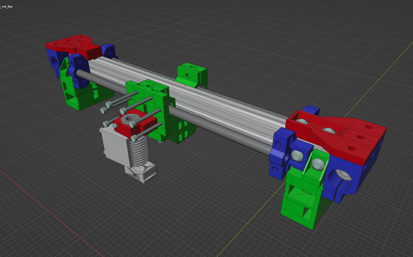
Designing the X gantry and Y motion system
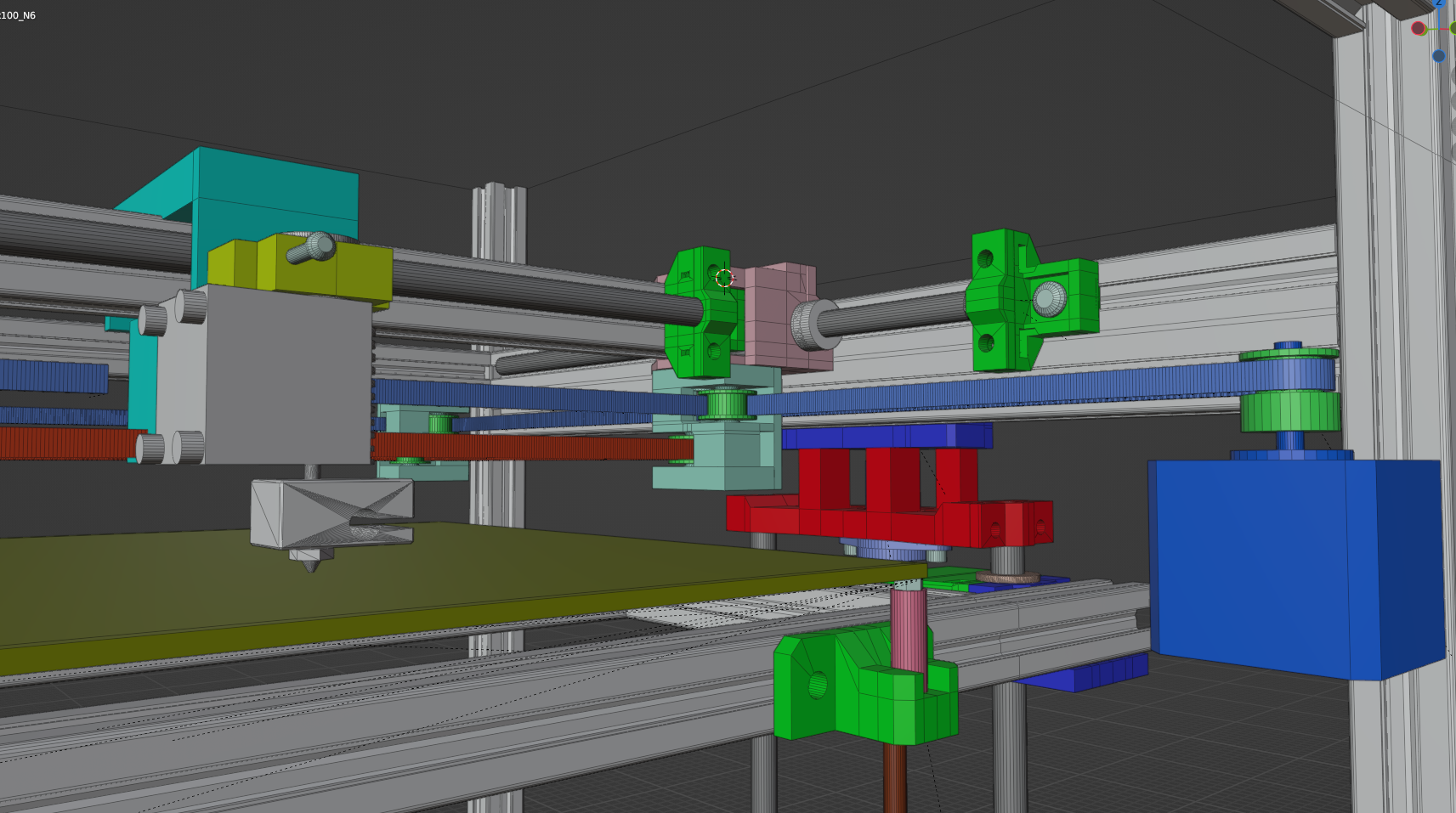
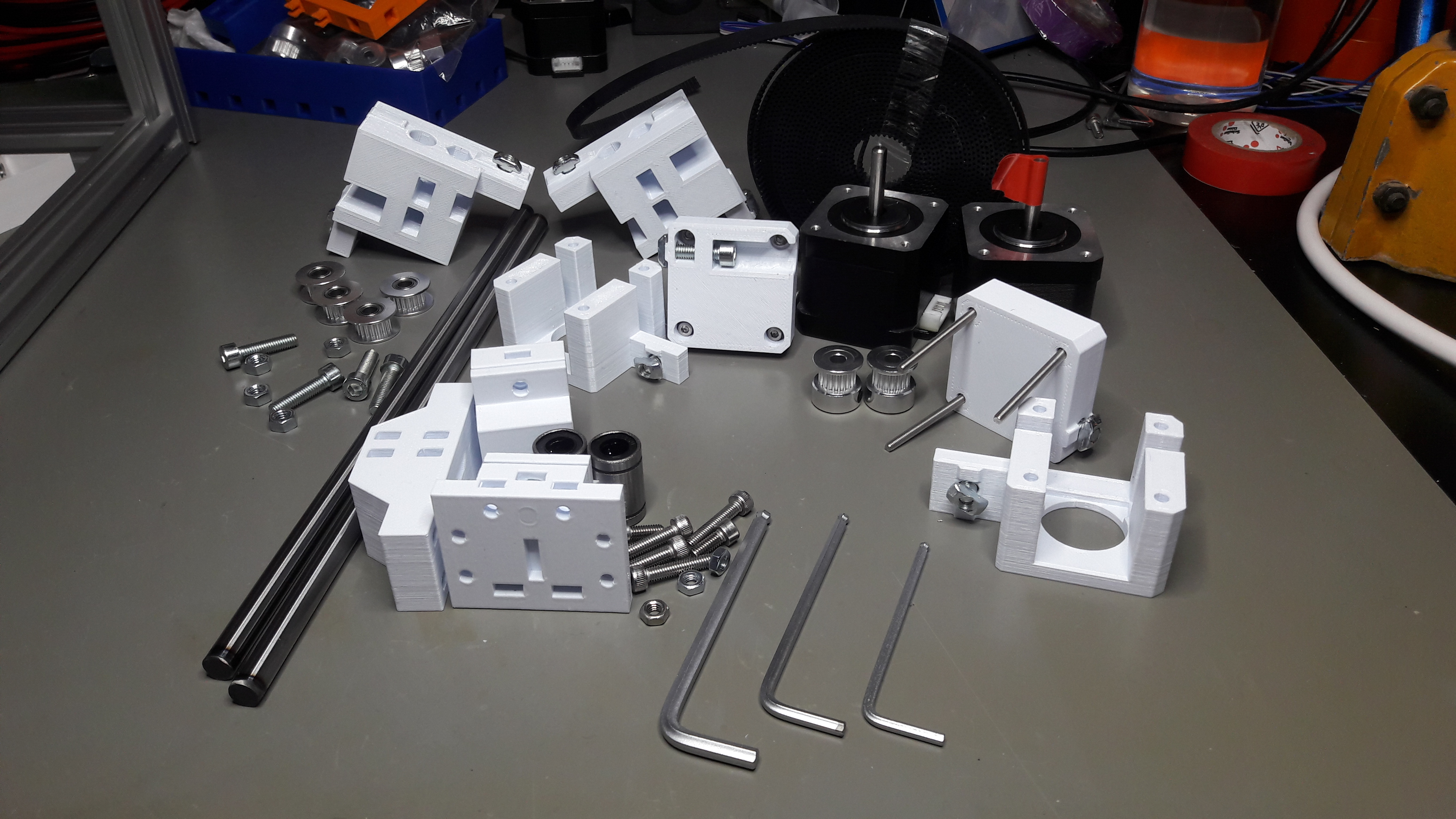
The following parts would make up the whole motion system. You can see the Y rod mounts, the X rod mounts, the carriage for the X gantry and where the pulleys are going to be located.
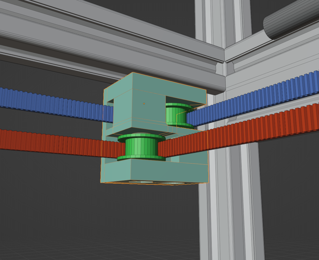
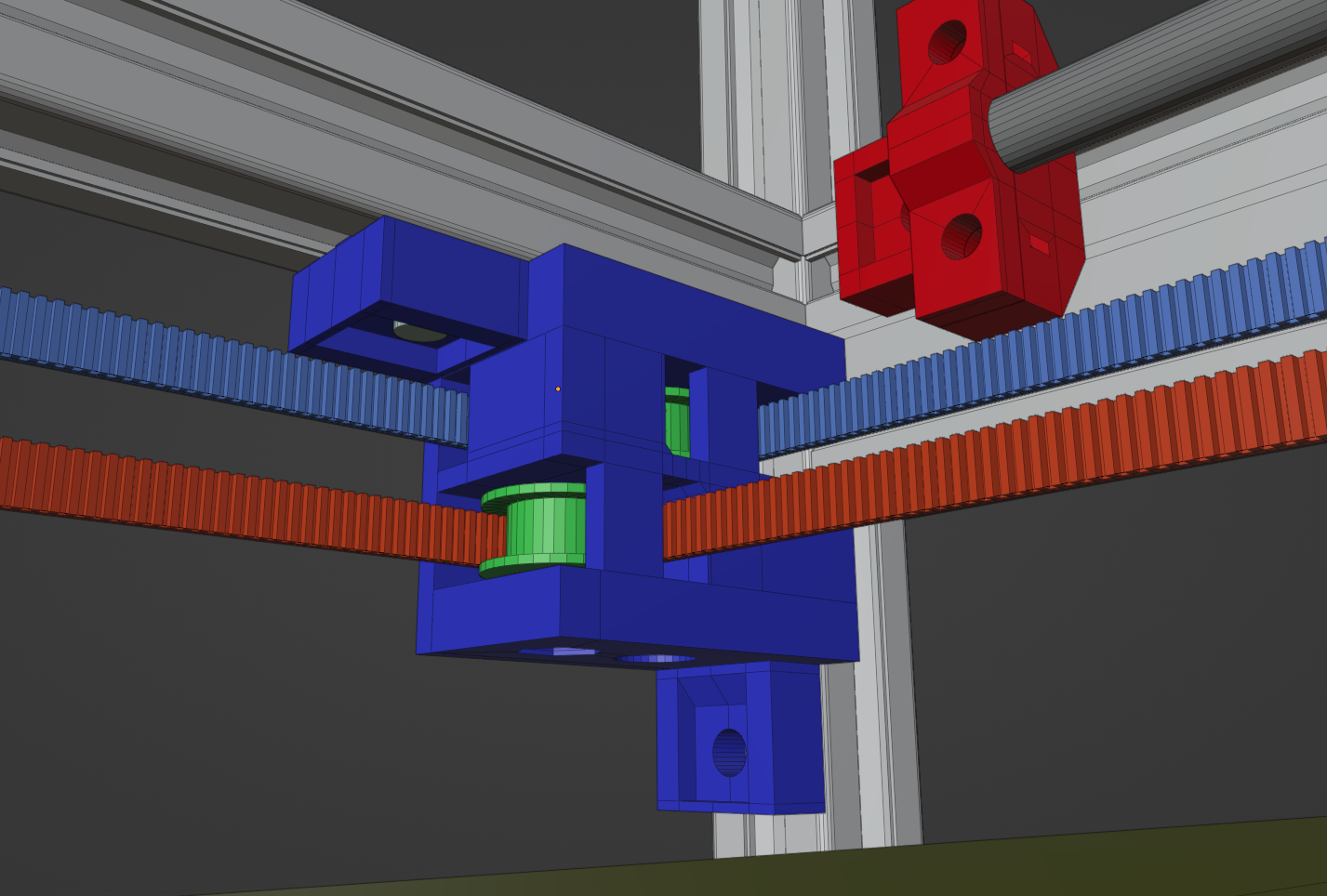
I had a finished pulley holder now, and the question now was how to attach it to the X gantry properly.
I made sure to model also the belts in Blender, so I can see where they would run.
I found a primitive way to attach the pulley holder to the X gantry holder part. It was simple and could be done with a M4x10 screw.
Originally I wanted to load two LM8UU bearings inside one part. Unfortunately 3D printed parts are too inaccurate to hold two LM8UU bearings next to each other without skewing them. The inaccuracies were too big, so that the bearings would bind a bit when pulling them along the rod. I decided to leave out the second bearing and just have one LM8UU bearing in the middle. It turned out to be fine with one LM8UU after all.
Another problem became visible when assembling it though. The part I so carefully designed cracked a bit too easy under the M5 screws. Partially the 40% fan for printing the PETG was to blame for sure. But I wanted to find a better way to design the whole part.

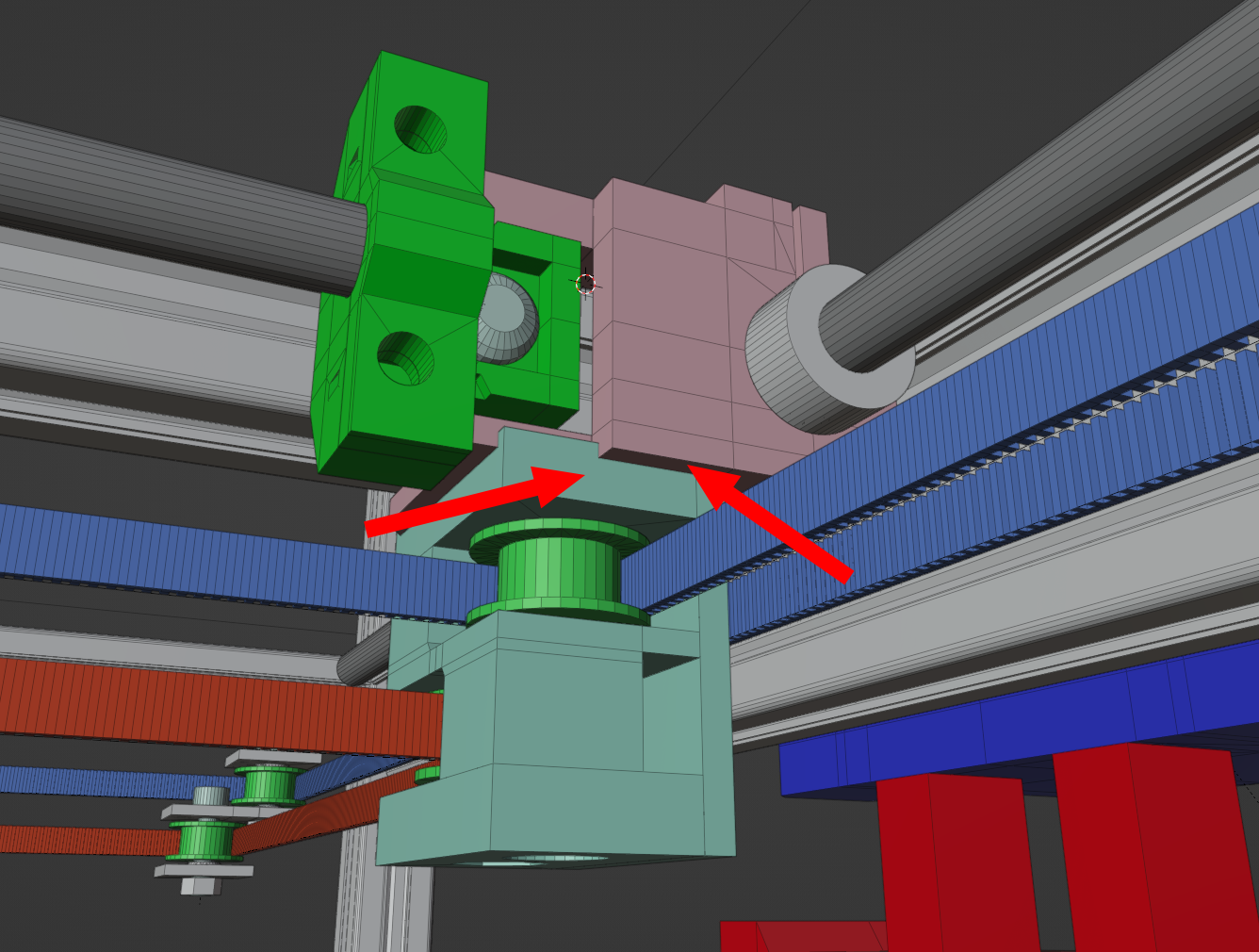
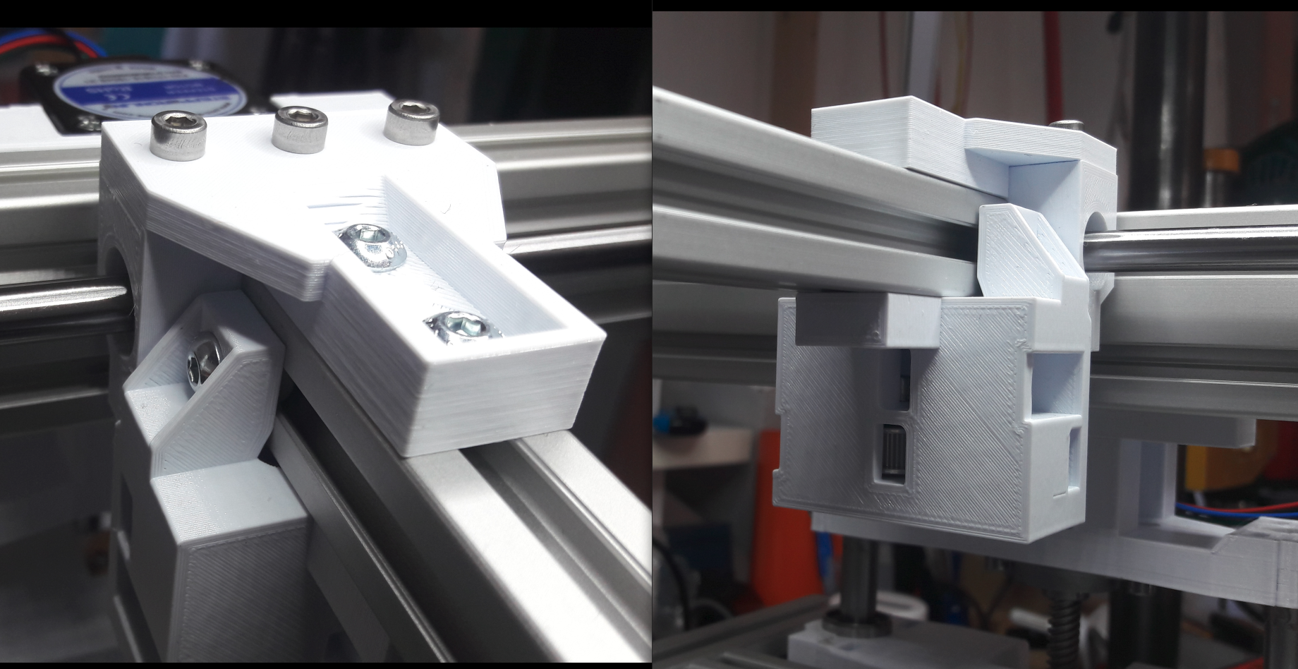
Mounting the X gantry to the Y rods was completely overhauled. The new design would use one flat part at the top to connect the Y bearing with the X gantry directly with 3 M4 screws and two M5 screws on the X axis. This design allowed also enough play to assemble the X gantry square to the frame, while also providing enough stability.

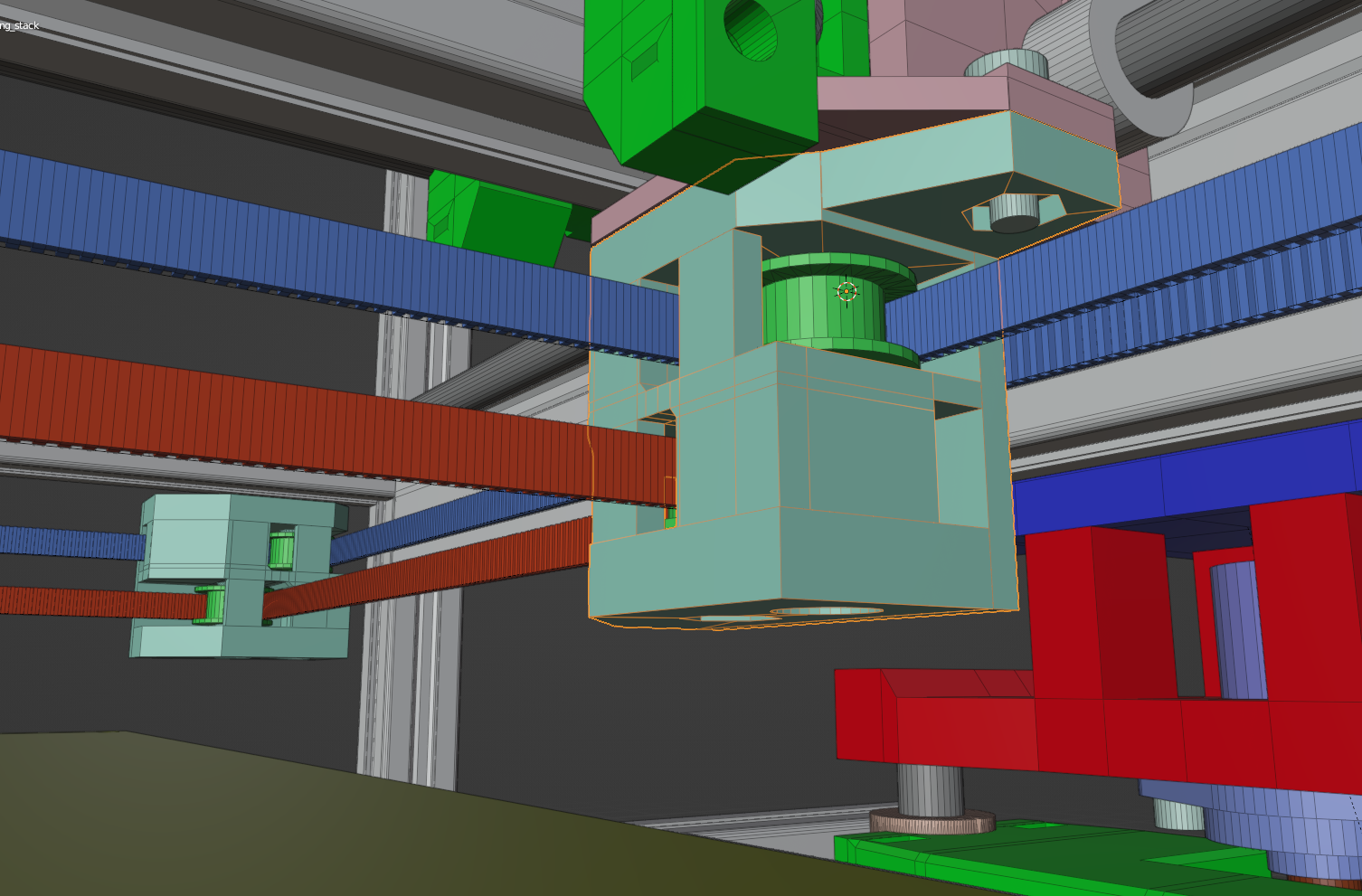
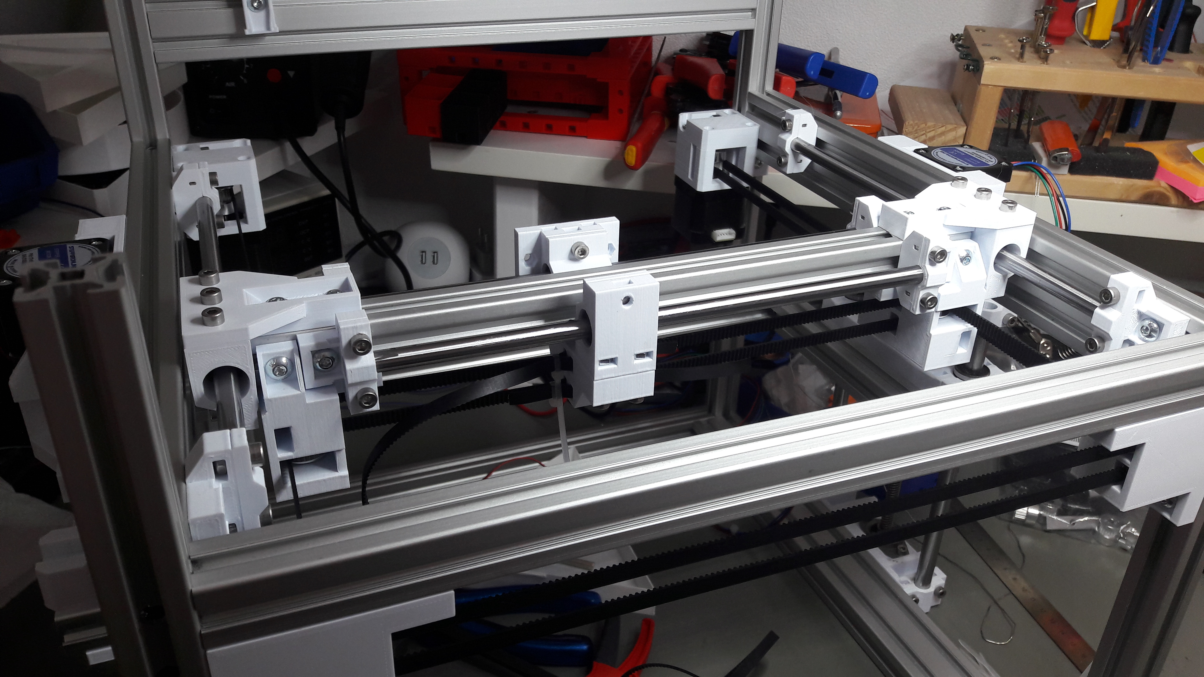
The pulley holder would not be connected with the bearing part anymore, but mounted directly to the X gantry profile with three M5 screws, two on the sides and one on the bottom. Here is what the finished assembly looked like:
After printing out the parts for the two Y rods and the left and right side of the X gantry I assembled everything. I was eager to check if the Y motion would work of if I would get any binding. Problems could have come from a not fully square frame or bad part design. But it would be fine as you can see in the following video:
Print Head Carriage, Motors and Frame Pulleys
The only three things that were left to do at this point would be a carriage for the print head. The pulley holders for the back of the frame and a way to attach the A/B motors for the Core XY motion to the frame.
I started out by designing a print head carriage. The belts would attach on the bottom of the carriage right in the middle. With six M3x35 screws I planned to attach everything I might need to the print head.
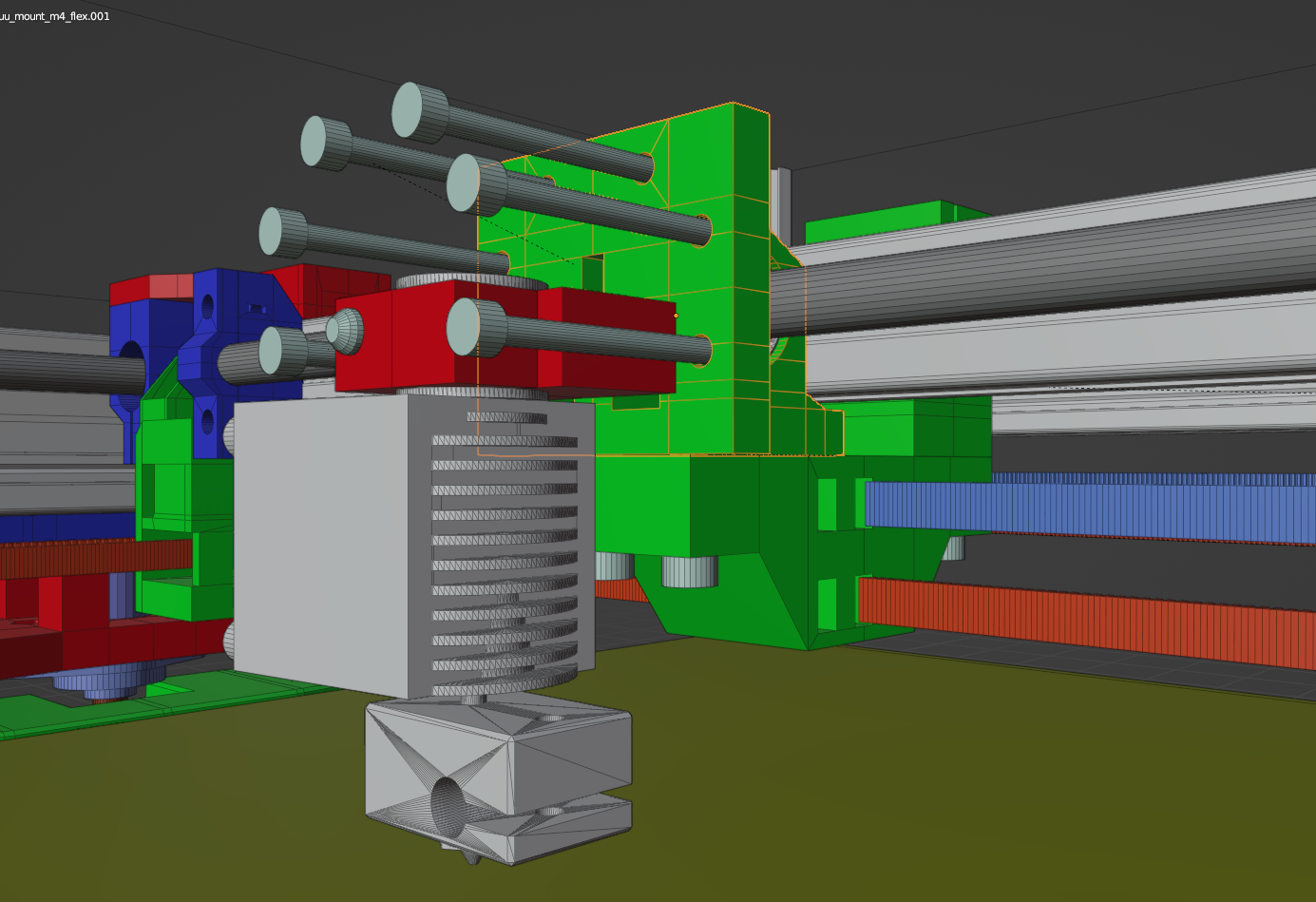
The finished X gantry would then look like this:
The rear pulley holders were quickly done:
Also the mounts for the A/B motors were rather quickly done. They would be my first layered part. That means the top would be screwed onto the bottom and the motor with four M3x35 screws. The resulting mount worked well in the end.
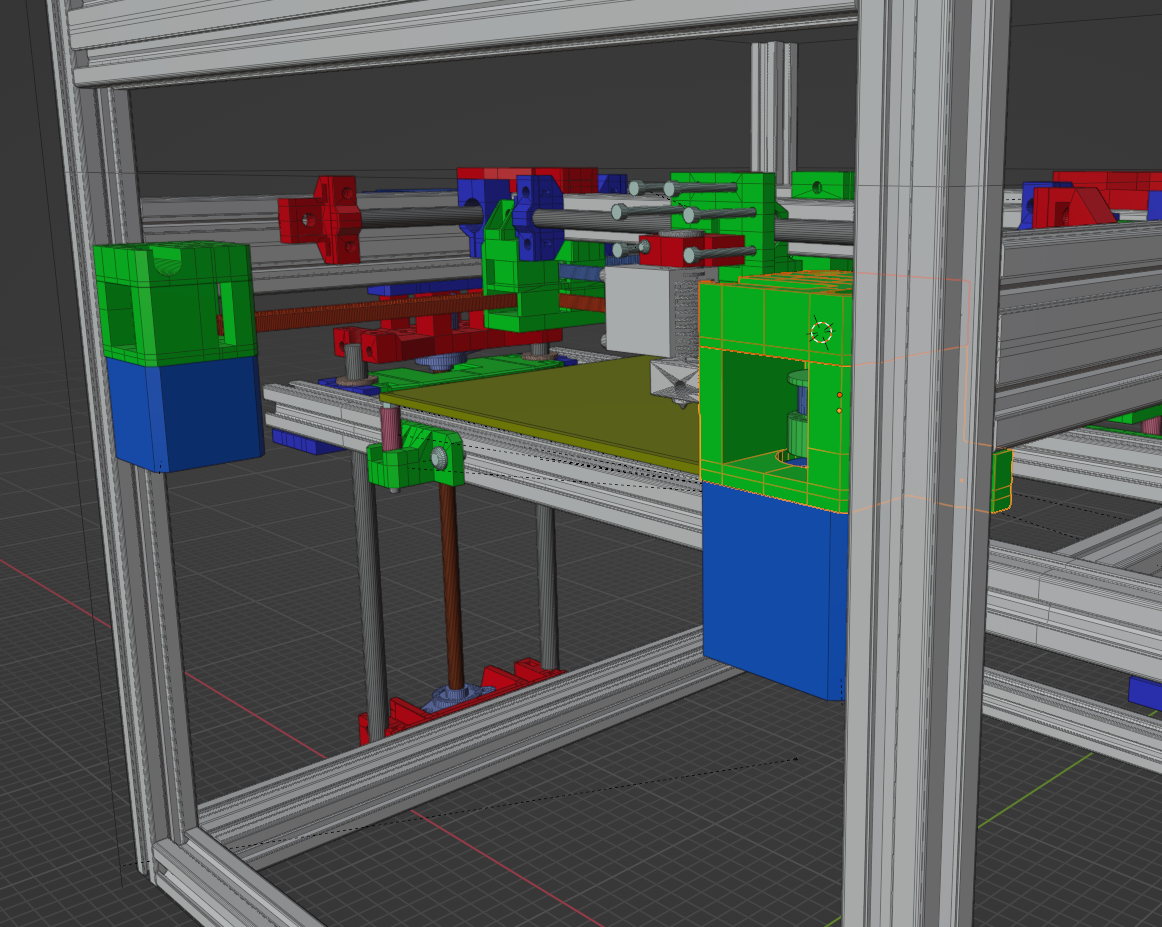
A few hours later and all parts were printed and ready for the final assembly of the Core XY motion system.
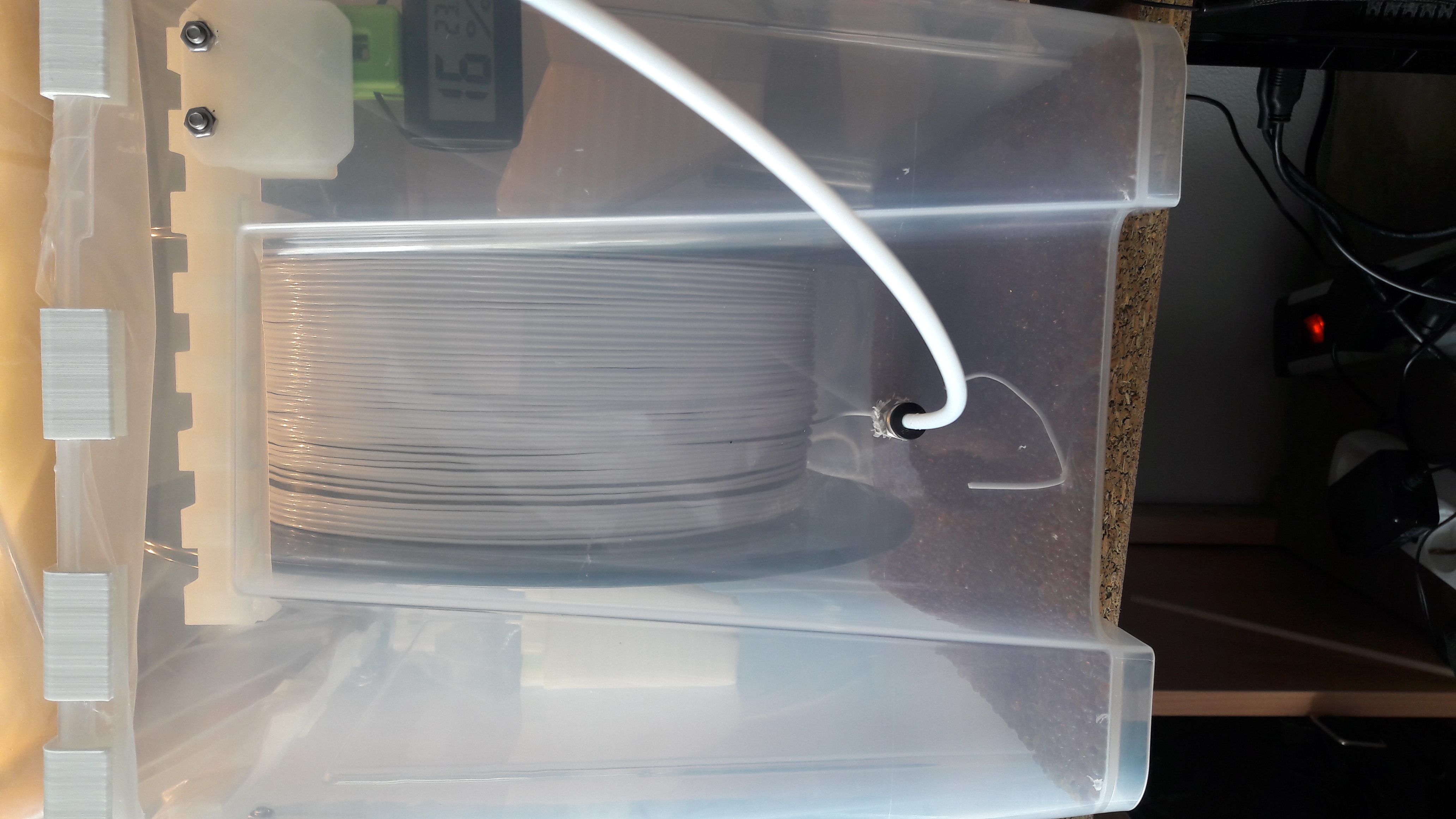
With all these parts finished, also my 2.3kg spool of PETG filament was finished. I managed to empty 2.3kg of filament for all the prototypes for the WeirdCube.
Core XY Belt Assembly And Test
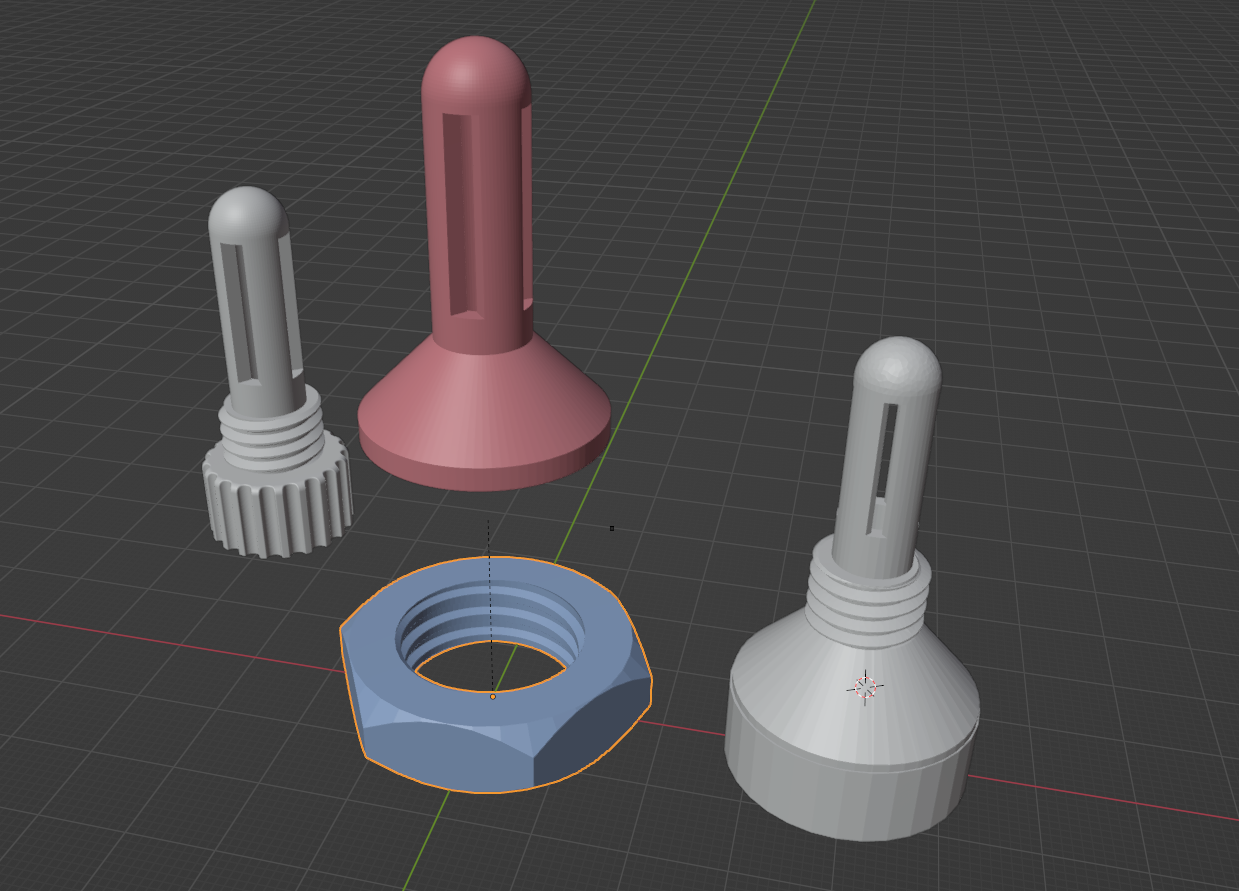
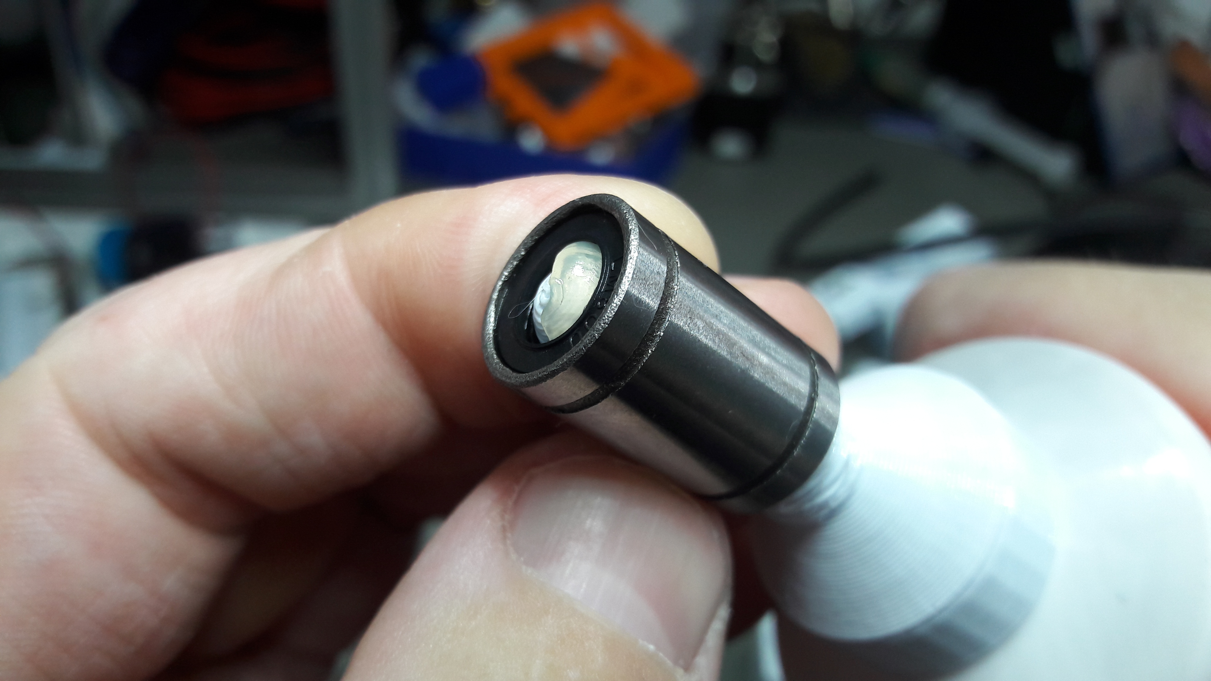
Before the final assembly I made sure to grease the LM8UU bearings properly. For this I had to remix a few LM8UU greasing helpers to fit to my tube of Nigrin grease. Luckily Blender has an awesome add-on for creating threaded screws and nuts.
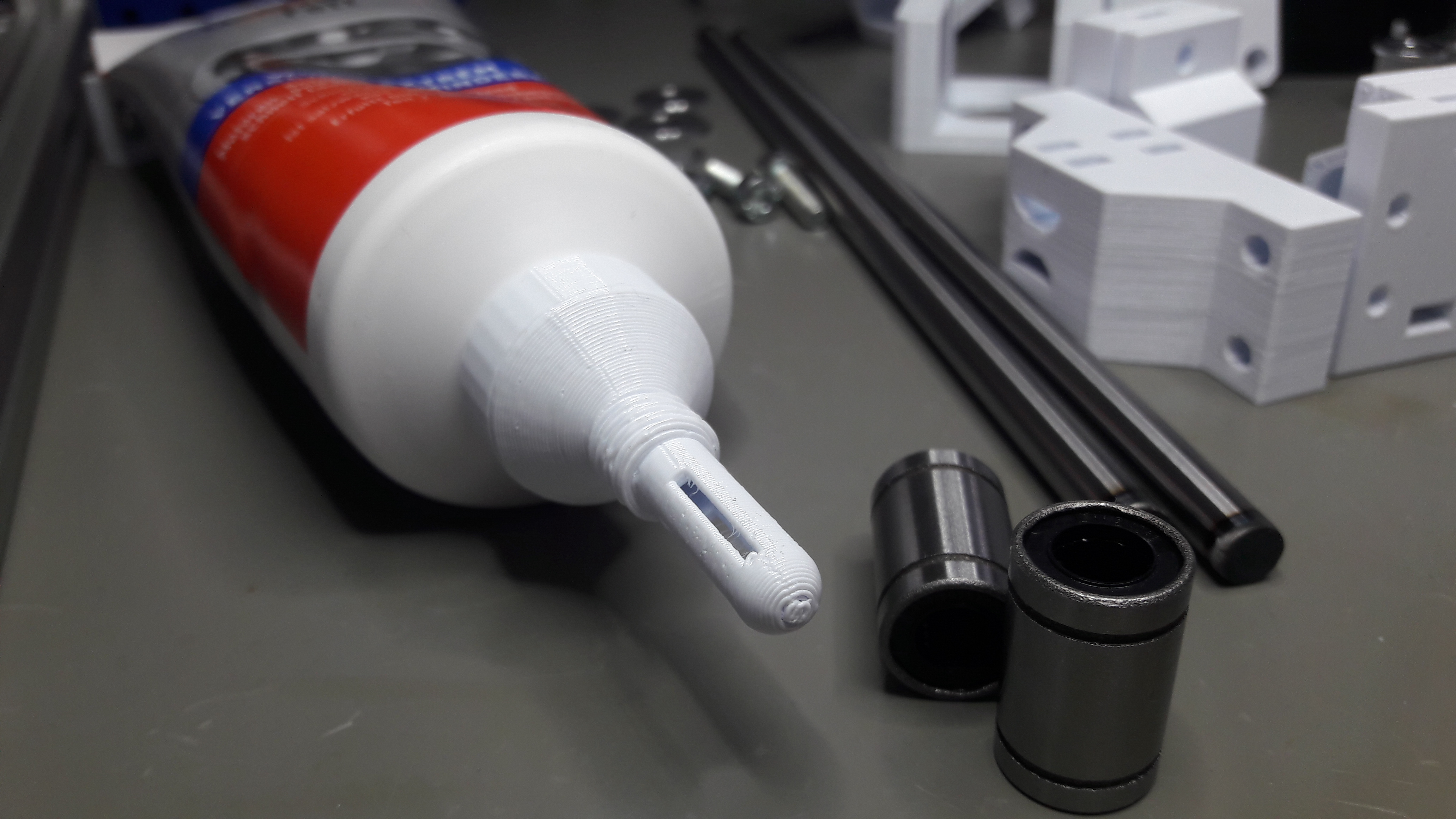
Greasing would be quickly and properly done with this helper.
Next I assembled the print head carriage, the pulley holders and the motor mounts.

I recorded myself assembling the linear rods on the X gantry here:
Also assembling and mounting the tool head I recorded:
After all the parts were mounted onto the rods I started running and tightening the belts.
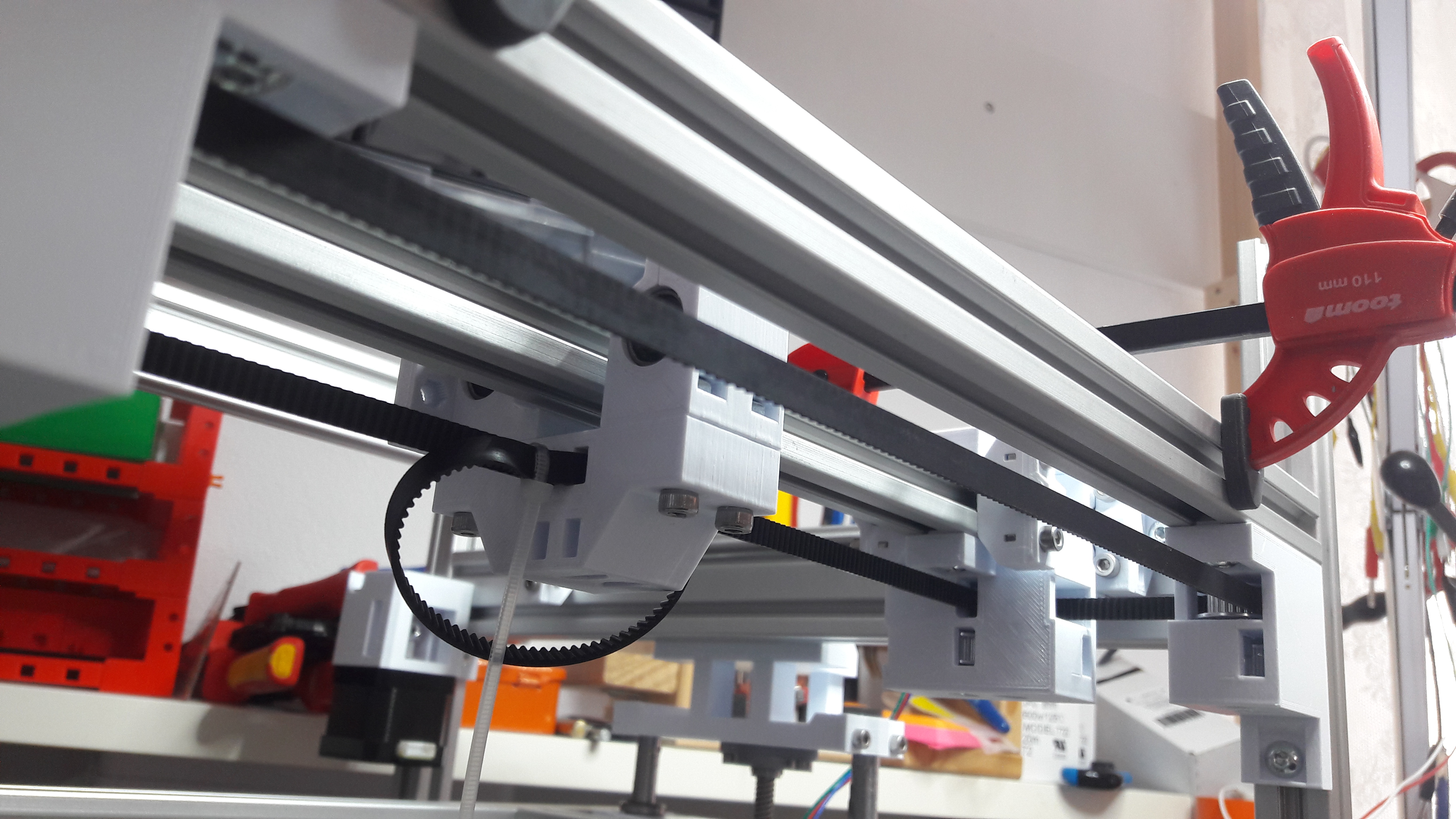
After running both belts the motion system was finally done.
I attached the motors to the mainboard, configured a Core XY motion system in the Marlin firmware and tested it next with my dial gauge. You can see me testing the Y and X motion in the following video:
This concludes the Core XY motion system for the WeirdCube. Next tasks are designing a print head, assembling the heated bed and adding a few end stops for proper operation of the printer.
