WeirdCube 3D Printer - Devlog 3 - The Z Axis and Mainboard
In this WeirdCube 3D Printer article I show the build of the Z axis, bed gantry and how I wired the mainboard. Building the Z axis was quite a challenge!
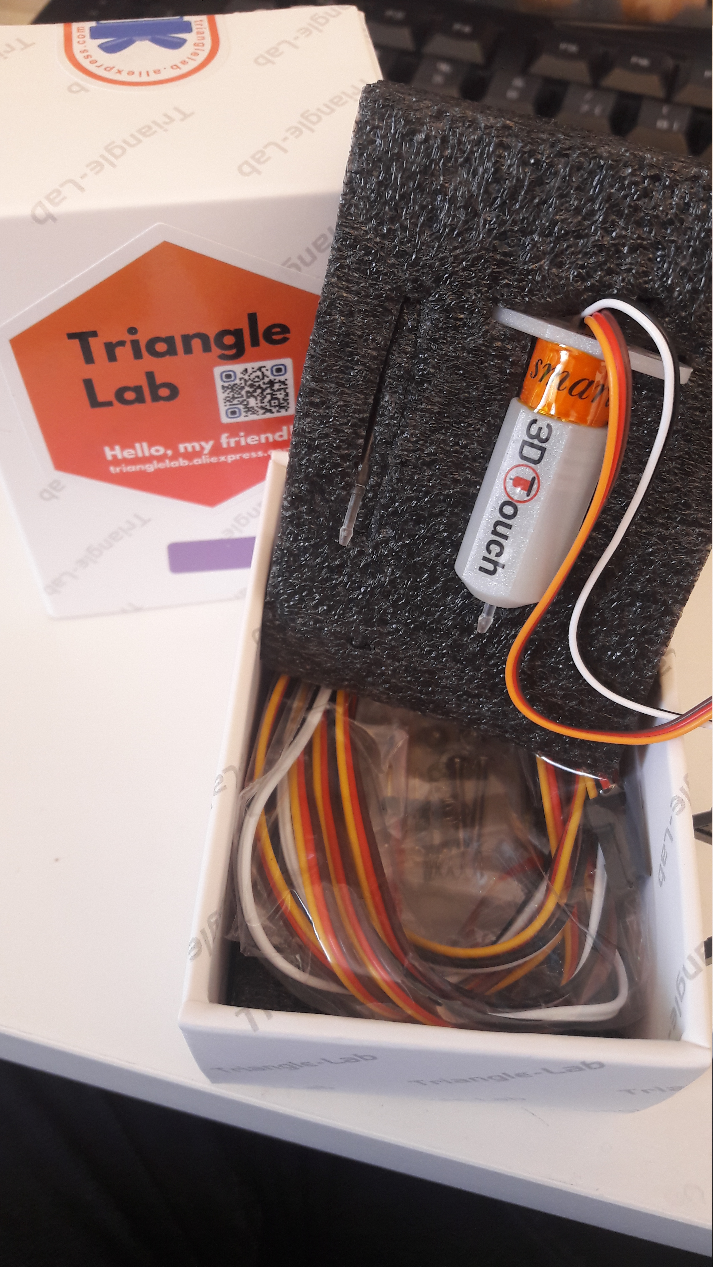
Let me start this article off with a piece of new gear! I ordered a 3D Touch sensor on Aliexpress for the whole bed leveling and Z tilt adjustment for the WeirdCube.
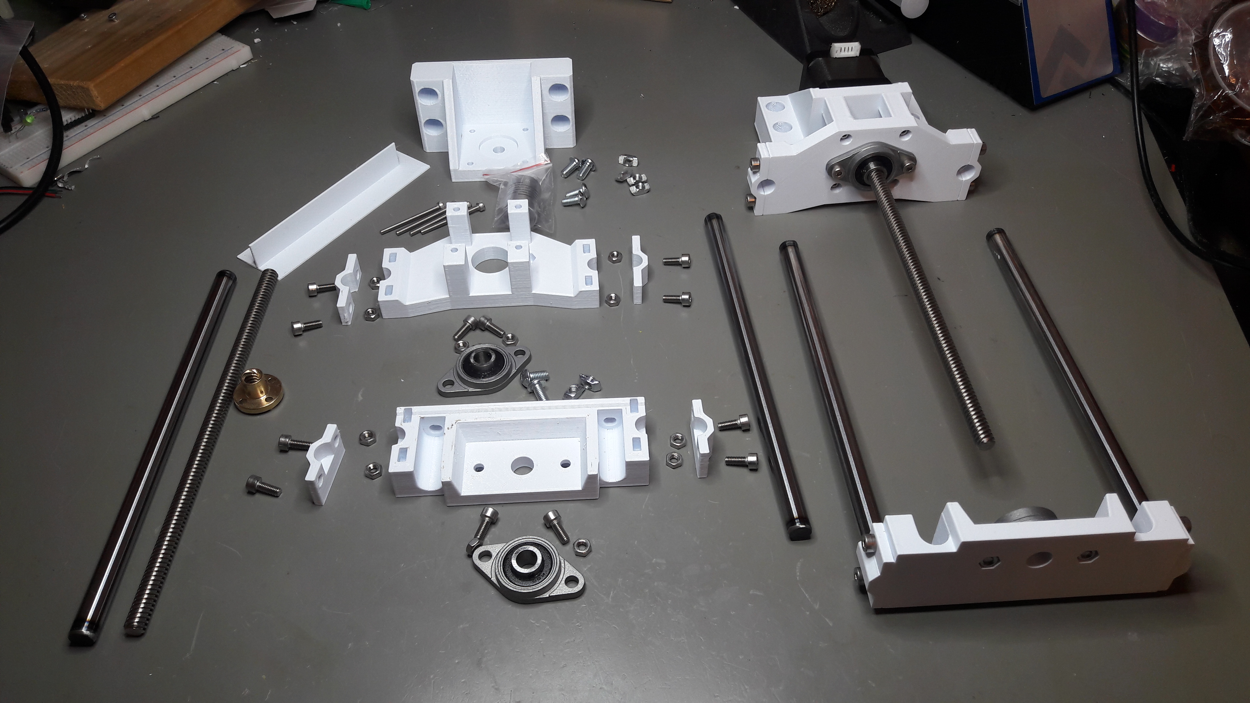
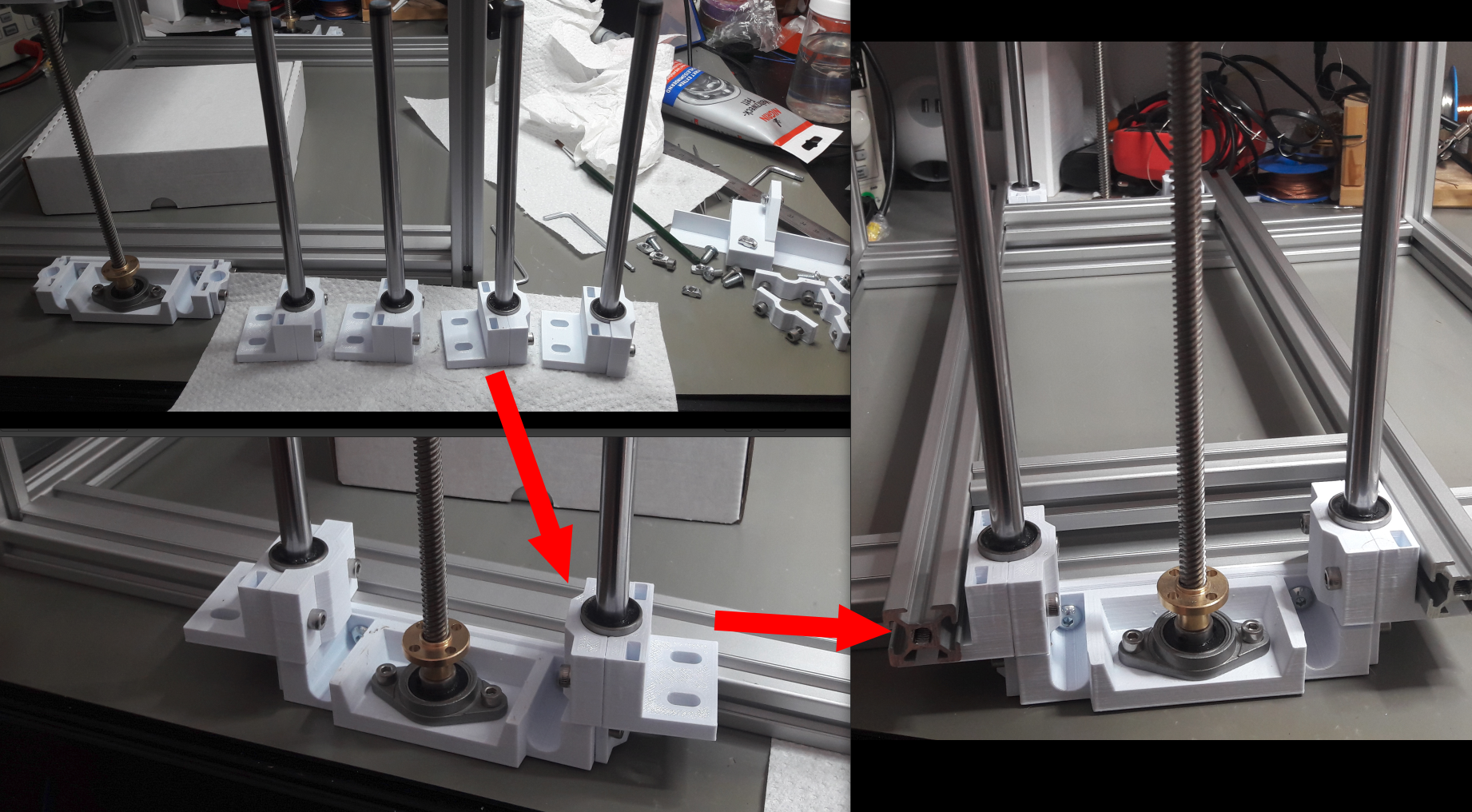
After the frame was built, I quickly started to design and print the first prototypes for the Z axis. WeirdCube will have two Z axis with linear bearings that sit ond linear rods and a Z screw for each of them. The Z screw is held by bearings that have grub screws to hold the Z screw, so that it does not apply force directly to the motor shaft.
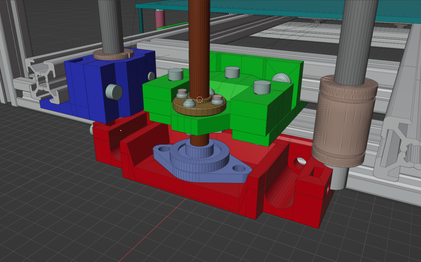
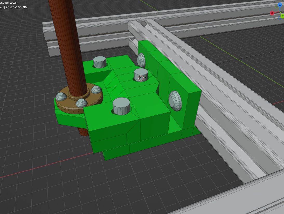
Lets go from top to bottom. At the top we have the stepper motor mount for the Z axis in blue. With 4 M3x35mm screws it holds the top axis mount part (in red in the image).
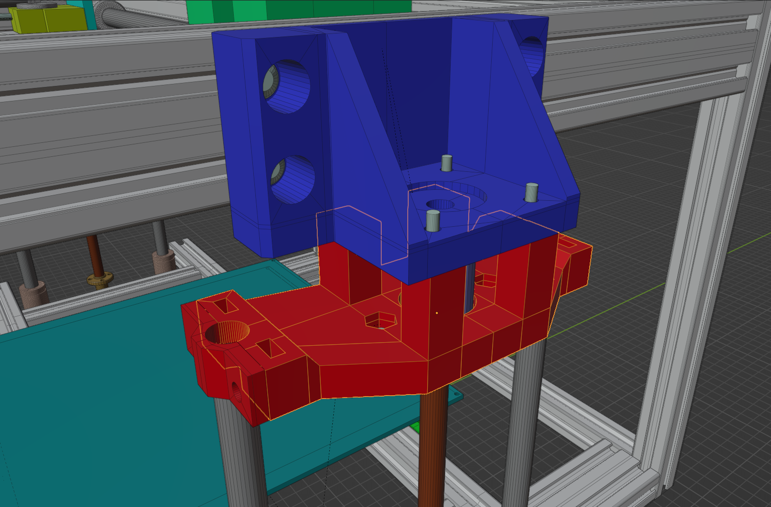
At the bottom we have the bottom holder:
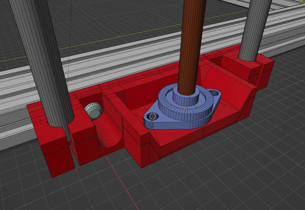
You will see later, that I changed the design of the bottom part a bit after I realized how well the linear rods were held by fixing it with screws.
Screw Nut Cutouts In The Bottom
I want to highlight a little thing, that I took me a few iterations in other projects. If you want to insert a nut at the bottom of a printed part, you usually have a very overhanging layer where the slicer tries to print the circles for the hole into air:
This overhang often leads to very messy holes after printing. And I like to print my parts without any support. By experimenting a bit I found, that I could give the slicer a few hints by inserting bridges already at the CAD stage.
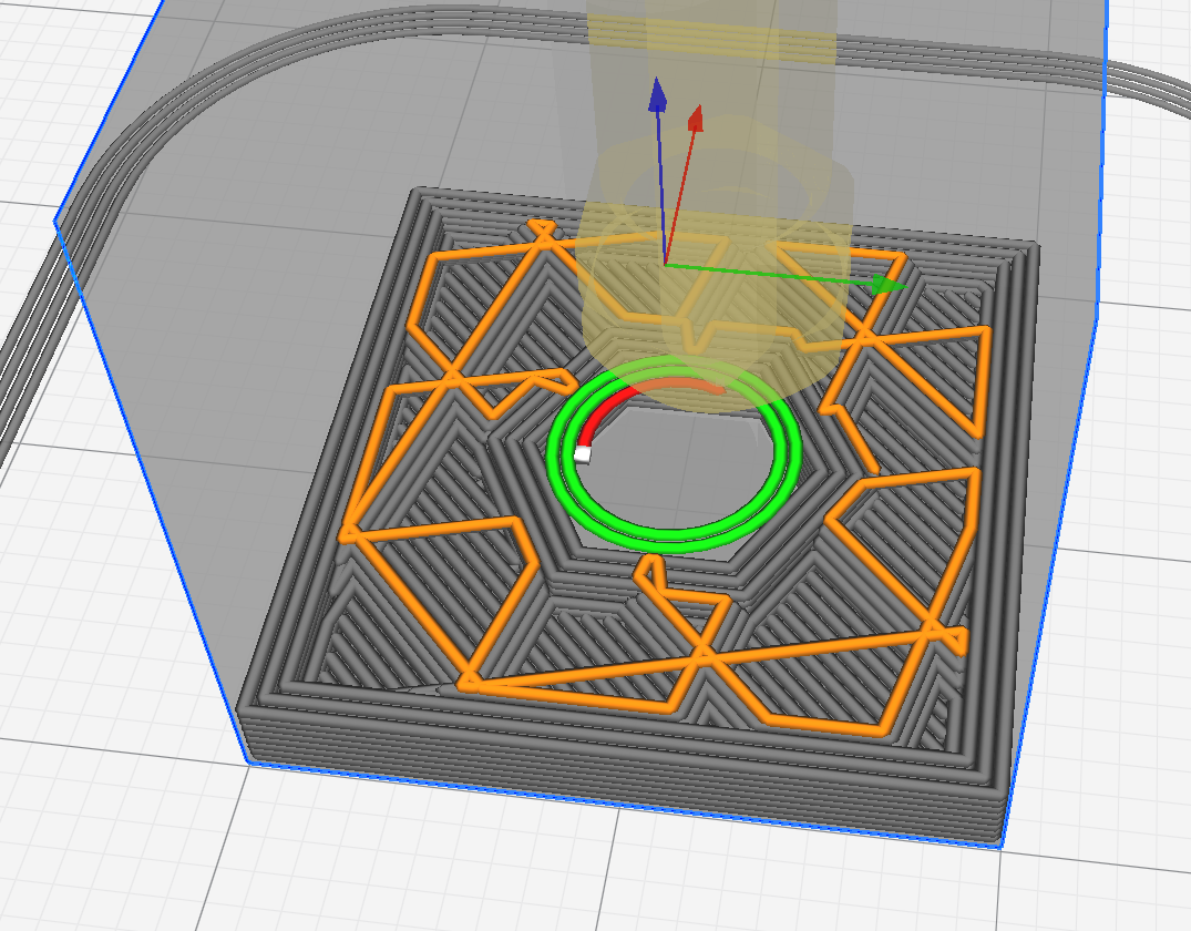
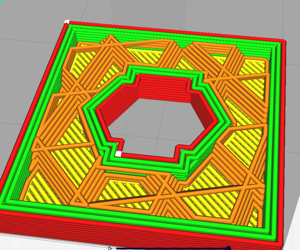
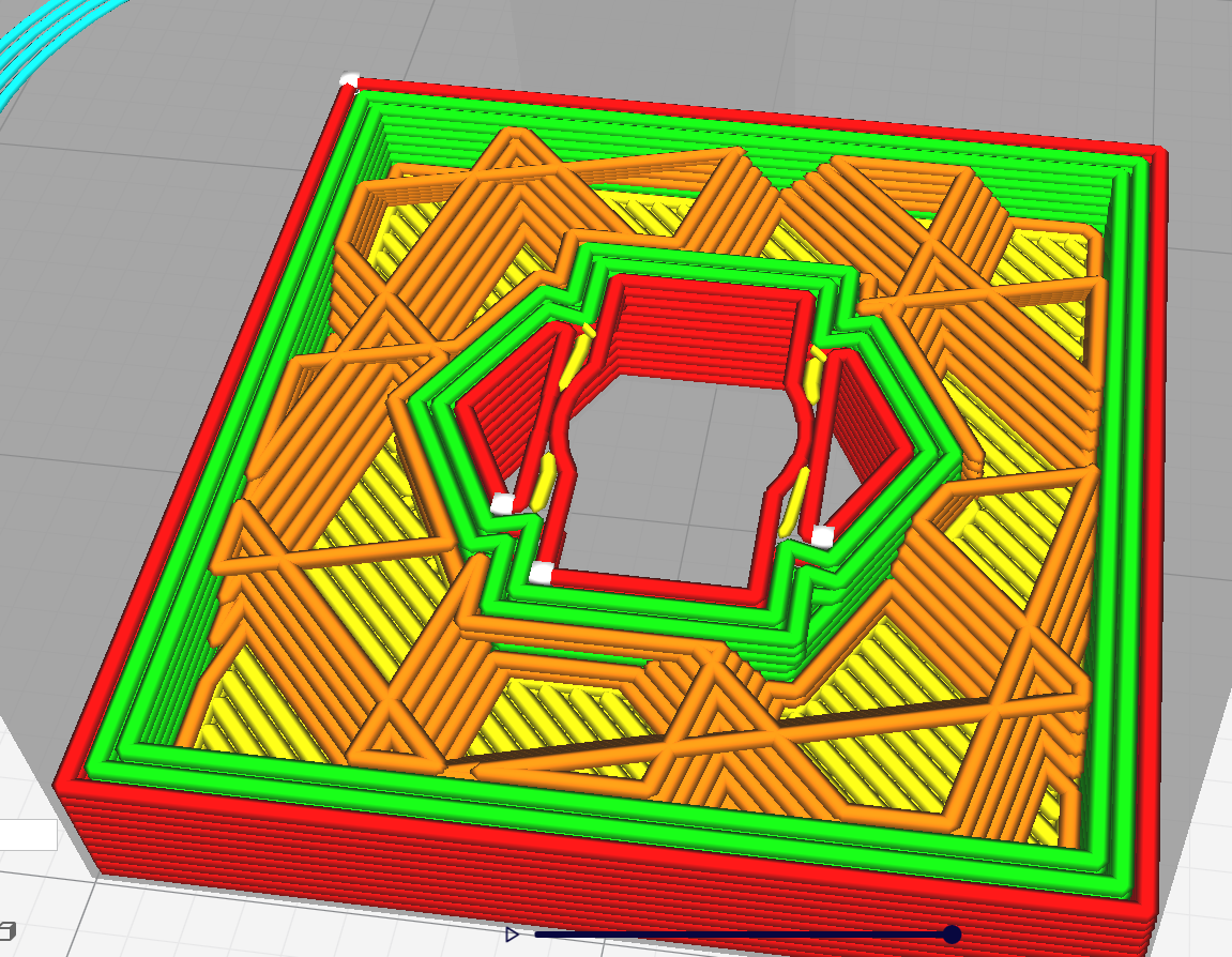
For this I cut a ramp and a bridge one or two layers (~ 0.6mm) under the top of the M4 nut cutout:
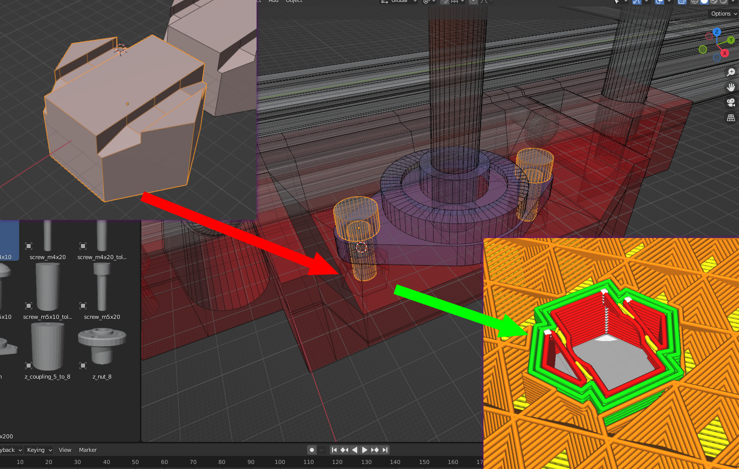
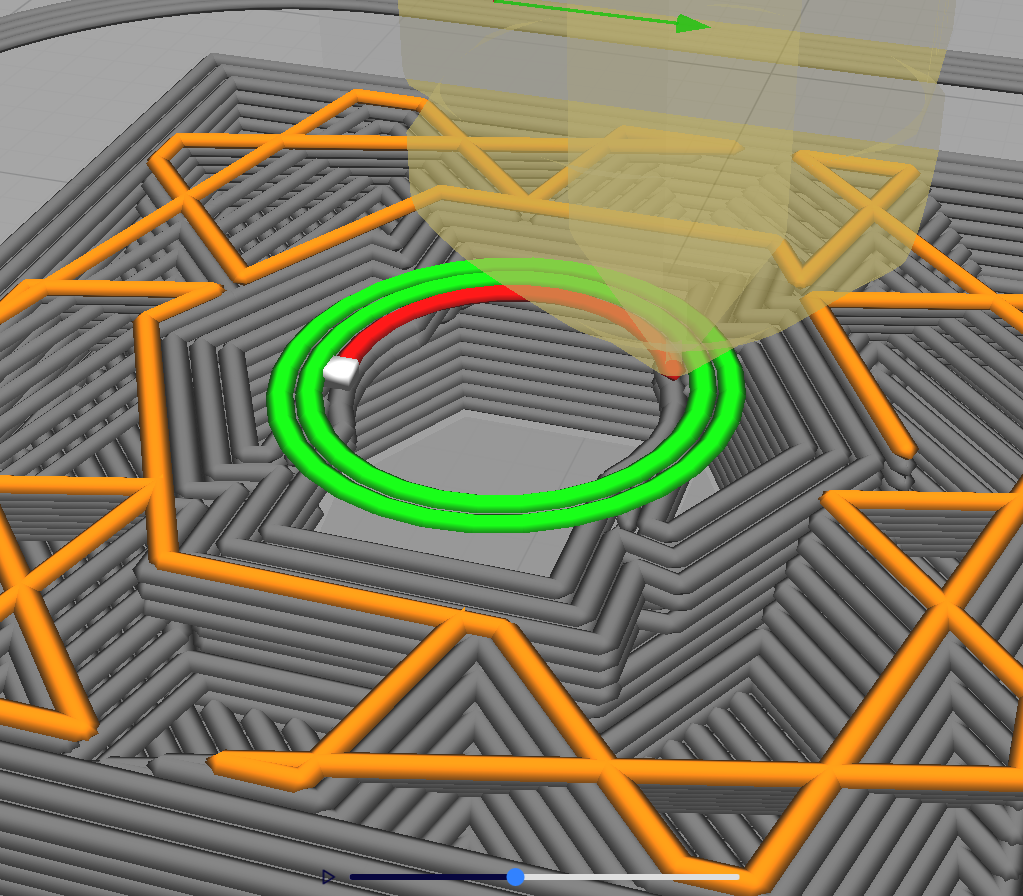
It makes the slicer insert proper bridges to lay the hole on:
Z Axis Prototyping
After the first models of the Z axis were made, I started printing the prototype of the Z axis. Here is the printed first version of the Z axis bottom holder:
The stepper motor mount were printed next and I added it to the frame:
I modeled the top holder for the Z rods next. I changed my idea of friction fitting the rods to a mount with 2 M4x10 screws. Which I then applied to the bottom Z axis holder too! The top holder would be mounted with 4 M3x35mm screws directly to the motor.

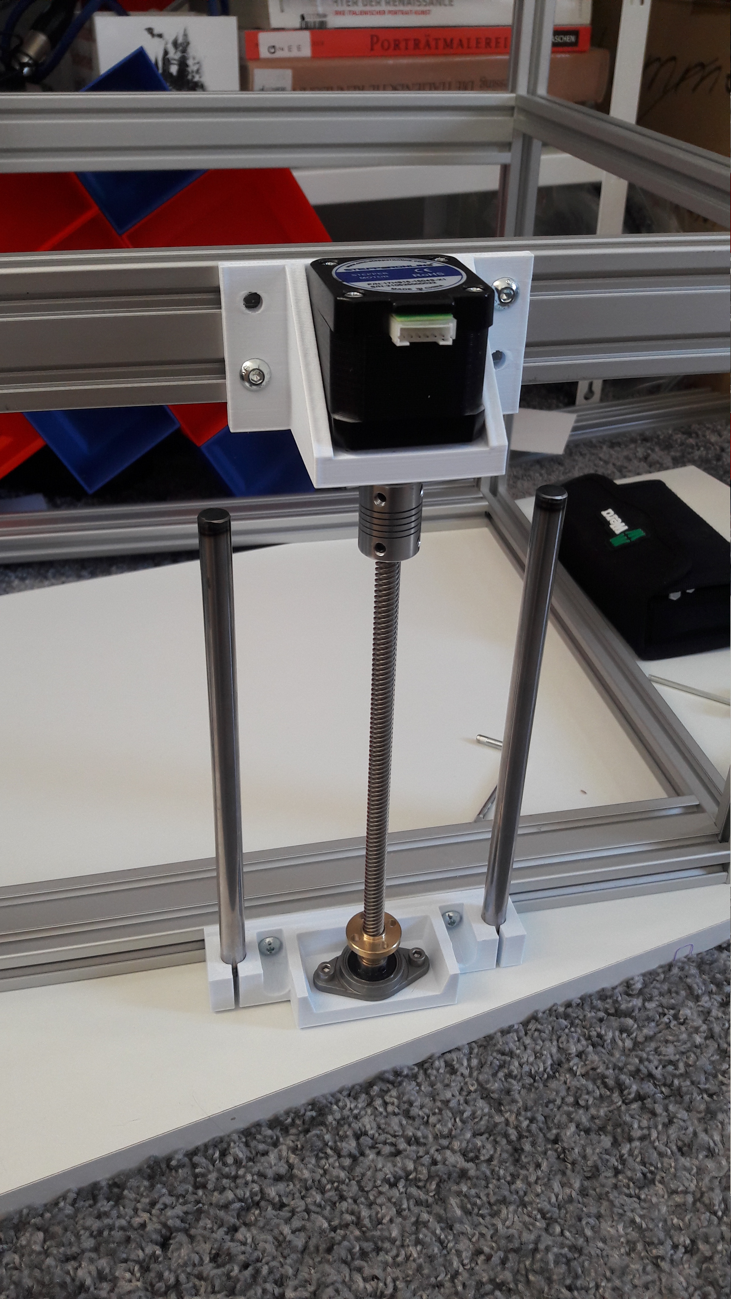
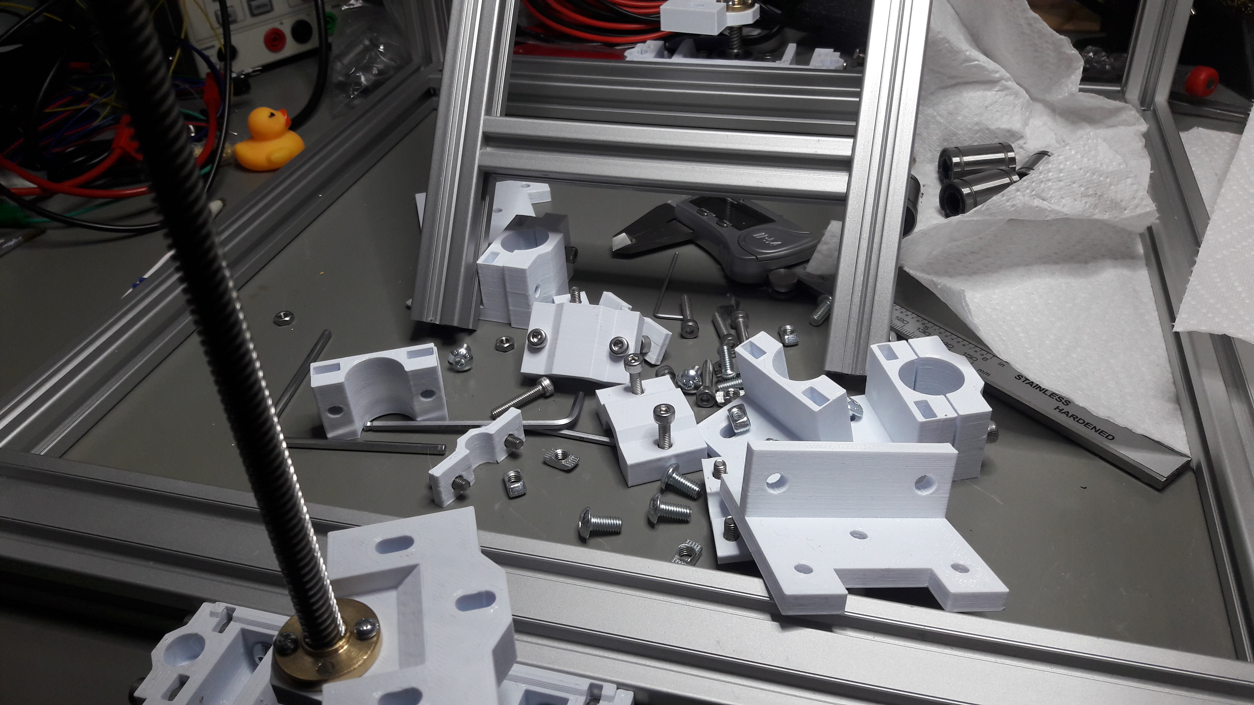
Next step was to print it all out and assemble it to see if everything fits as intended.
And then assemble everything to the frame.

There were no problems encountered and this design turned out to work nicely. I designed and printed a helper piece for positioning the motor mount on top and the rod holder on the bottom on the frame. It has two lengths, one for the motor mount on top and one for the bottom holder.

Design Of The Z Bed Gantry Mount
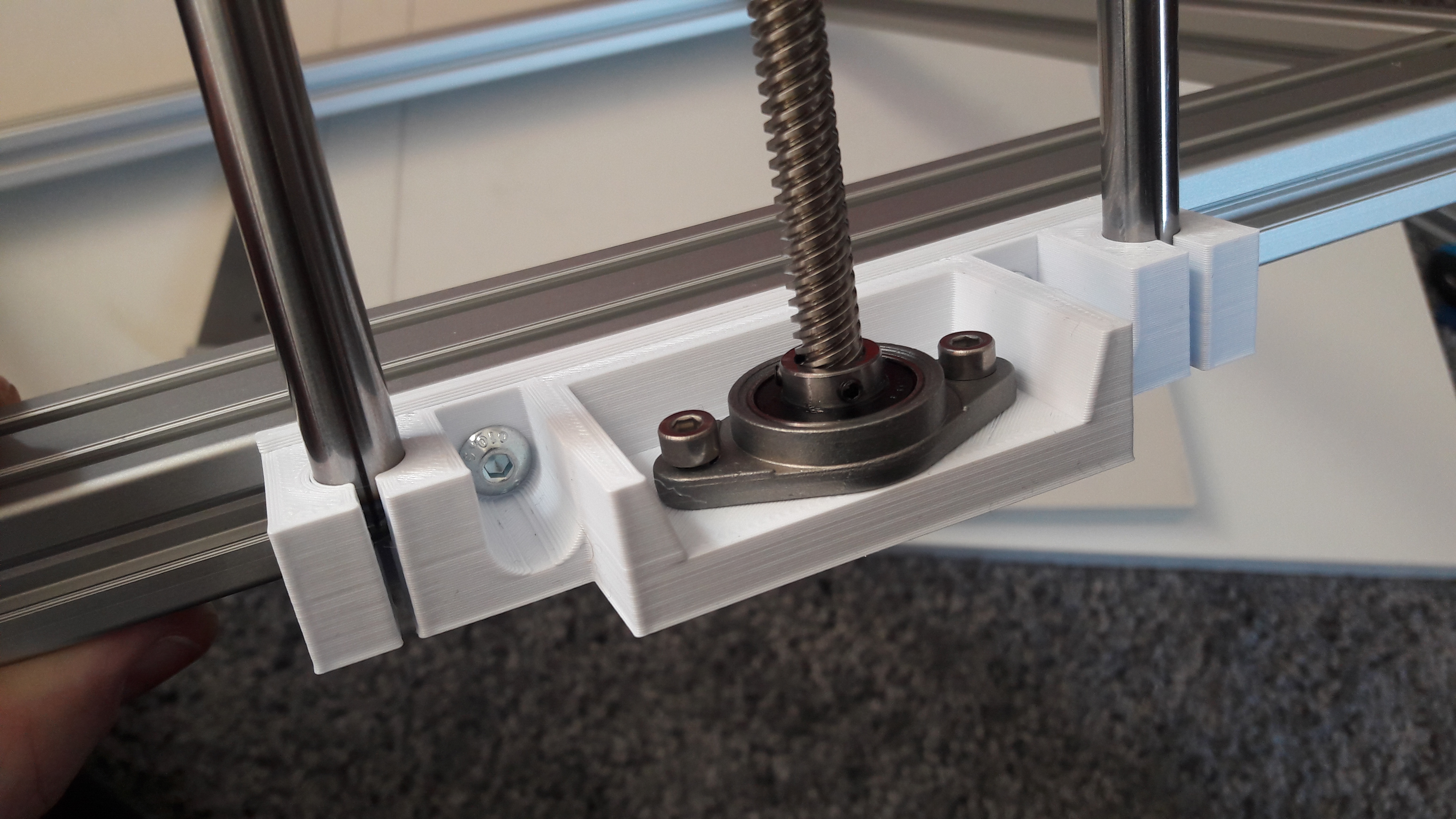
Next up was the first iteration of the linear rod bearing holder and guide for the print bed. As well as the Z nut holder to push/pull the bed up/down. I started with modeling a holder for the LM10UU bearing and then added an adjustable Z nut holder.
I printed the parts and assembled them and started testing a bit.
The bearing holders worked fine so far. And next up was the Z nut mount. I designed it to leave some extra play for inaccuracies of the bed gantry construction. The reality was about 0.5mm off, so I had to design for some play.
Printing and testing was next. Here are a few steps of the assembly for the Z nut mount:
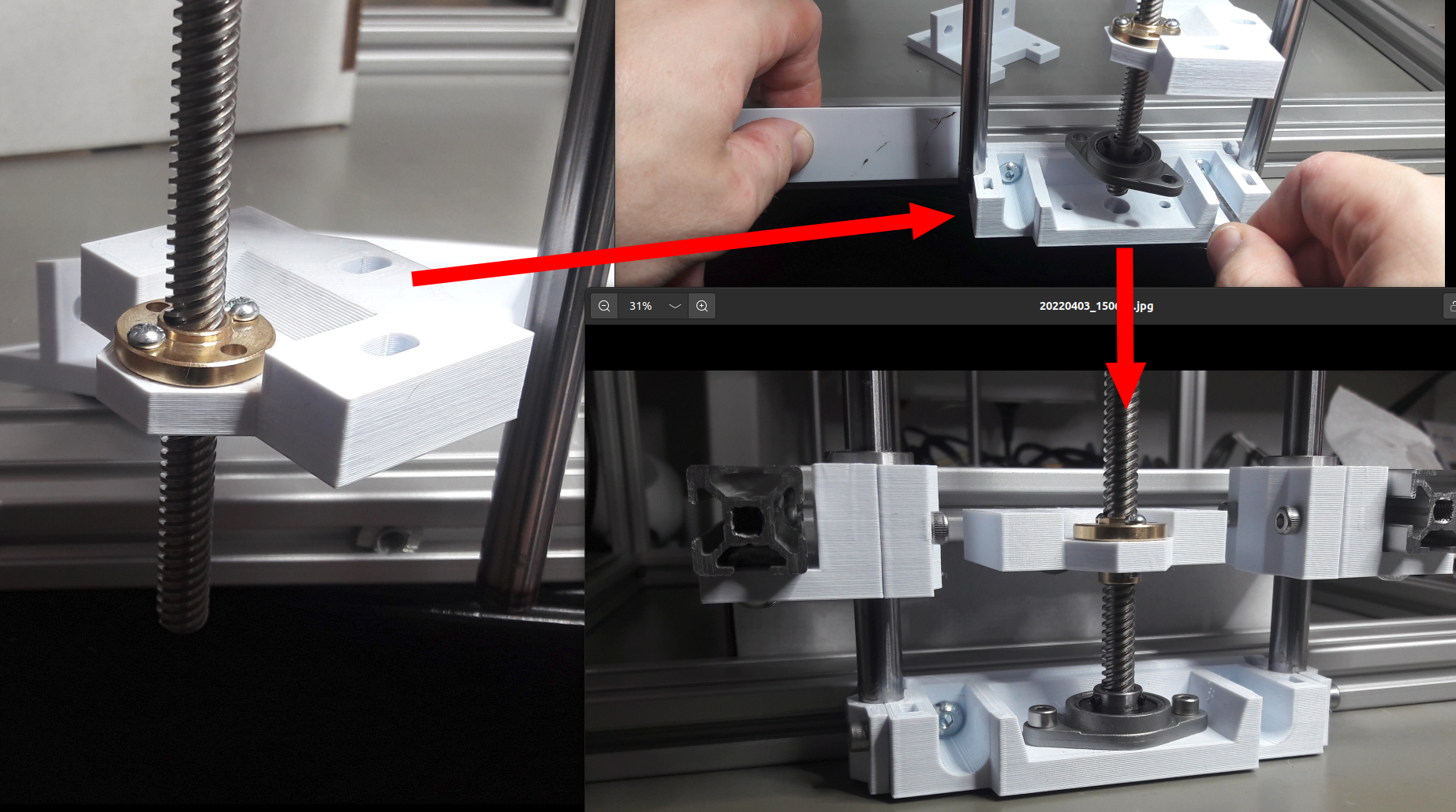
This was the first time I tested the whole mechanics and the Z screw, and it seemed to work very fine so far.
Next up was giving the motors some juice and see some real action.
Setup Marlin on the Big Tree Tech Octopus
My first choice as firmware for this 3D printer was Marlin.
But first I had to assemble the hardware and add some cables. Here is the design for my MakerGrid LCD12864 holder.
You can find the files for this in the WeirdCube Github repository: lcd12864_mount-base.stl.
Here are shots of the first setup of the mainboard and the display.
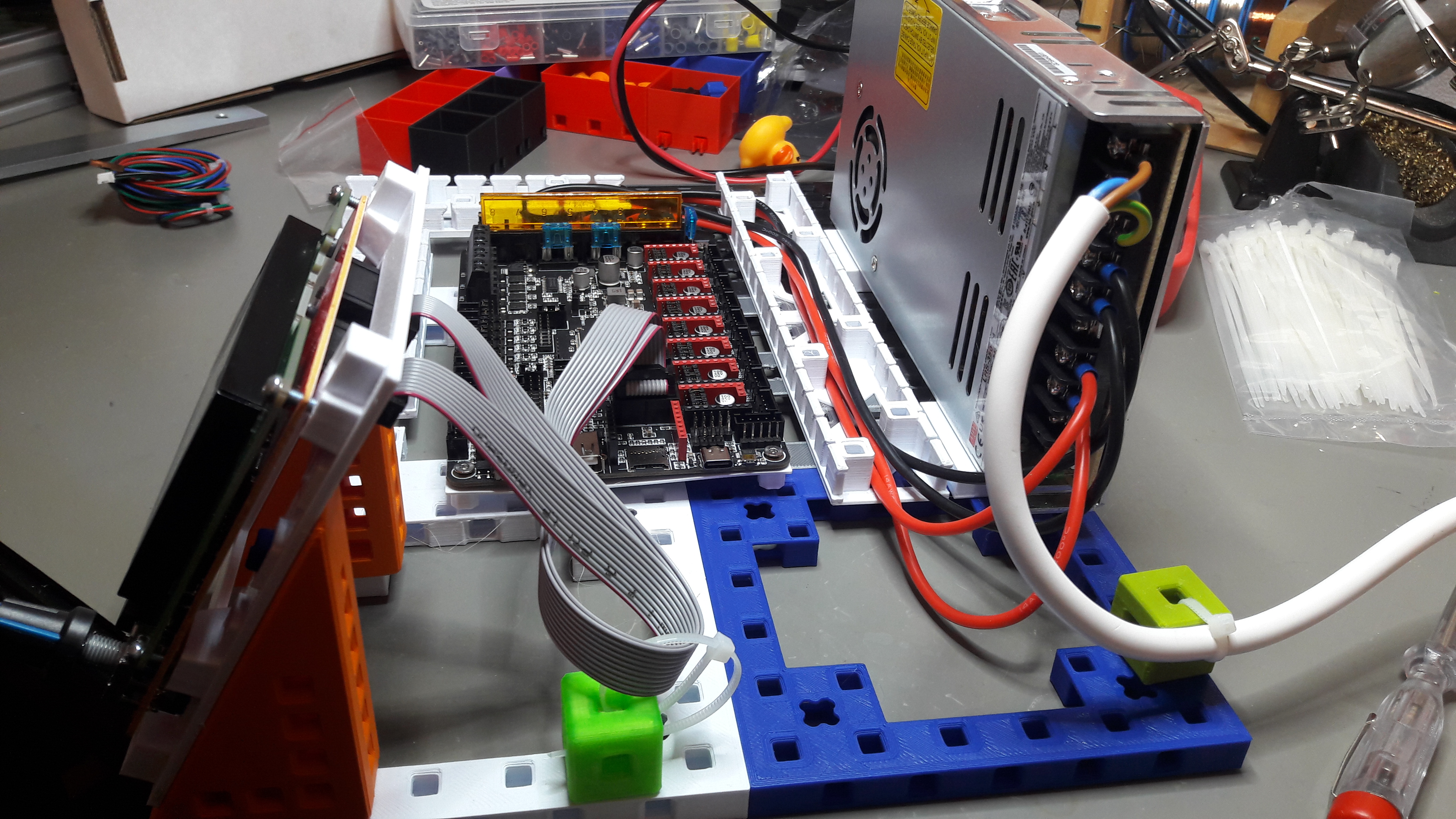
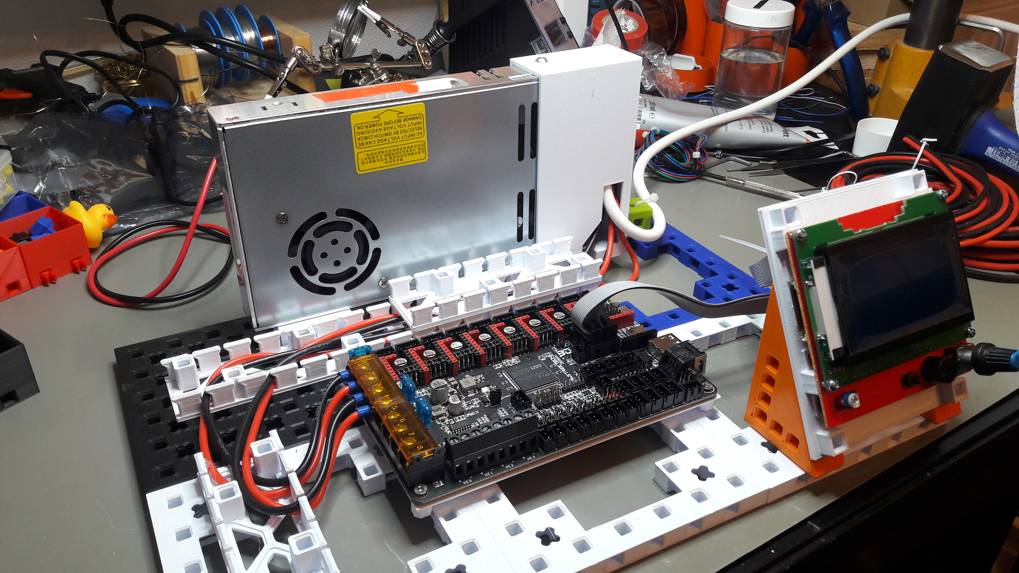
Compiling Marlin was not an issue, and after 1-2 hours I successfully uploaded a self compiled Marlin firmware and got to check if the motor drivers would work.
Unfortunately on testing I noticed that I could not get the extruder motor (Motor 4) to work at all. More and more testing revealed, that it was not a hardware issue with the stepper drivers or the motor, but a software issue. I swapped pins around in Marlin until I was sure it was not the hardware.
I was not the first one to stumble across this problem with Marlin and the Octopus mainboard.
- Marlin - (E0 on BTT Octopus won't extrude) #23053
- Marlin - IDEX Printer - E1 does not work - BTT Octopus pro board #23725
- Marlin - dual Extruder Problem e1 dont Work #22714
And there were several other issues. Diving down these reports did not reveal any way forward with Marlin. While I am a confident C/C++ programmer, I did not feel like hacking on Marlin until I get this to work. So for the future I will consider using Klipper for the WeirdCube 3D printer.
But anyways, moving motors looked motivating and connecting the Z motors was just one step away. So next up I tested if the Z axis would work at all.
The Cheap Bearings From Motedis
When testing the Z axis, I noticed that the axis was somtimes stalling a very very tiny bit and then rattle a bit. It's hard to show, because it was only a faint vibration you could only mostly hear and feel. But I tested the LM10UU bearings. And it revealed the following problem:
There is definitively too much resistance when sliding the bearing on the rod. That is something you have to try and test yourself before realizing that this is not supposed to be. I compared the bearing with a different rod, but as it seems the other rod was of even lower quality and too thin:
I ordered new LM10UU bearings. This time from a brand that I could at least find on google: MSM LM10UU. Here is a demo video of testing the new bearings. They would slide very easily on the same rod as the other bearings from Motedis. The brand of the Motedis is largely unknown, I could not find any DZH LM10UU bearings via google.
Final Z Bed Gantry Design
Despite figuring out the bearings to be the source of the binding problems with the Z axis I decided to redesign the complete Z nut mount. So next up was disassembling the old Z bed gantry.
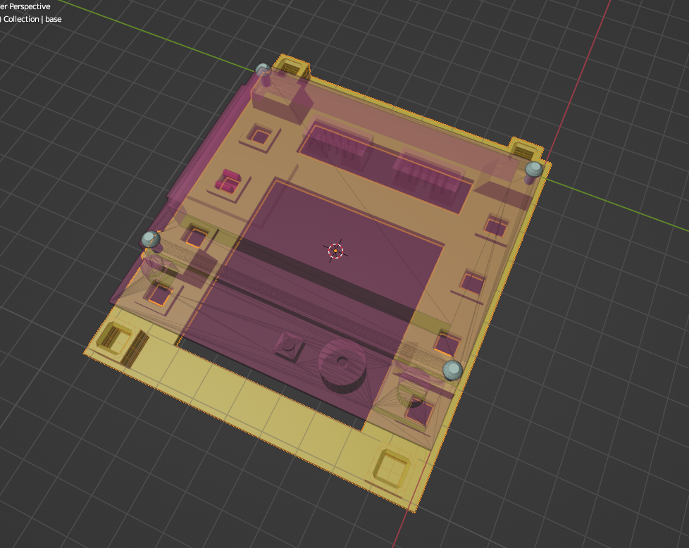
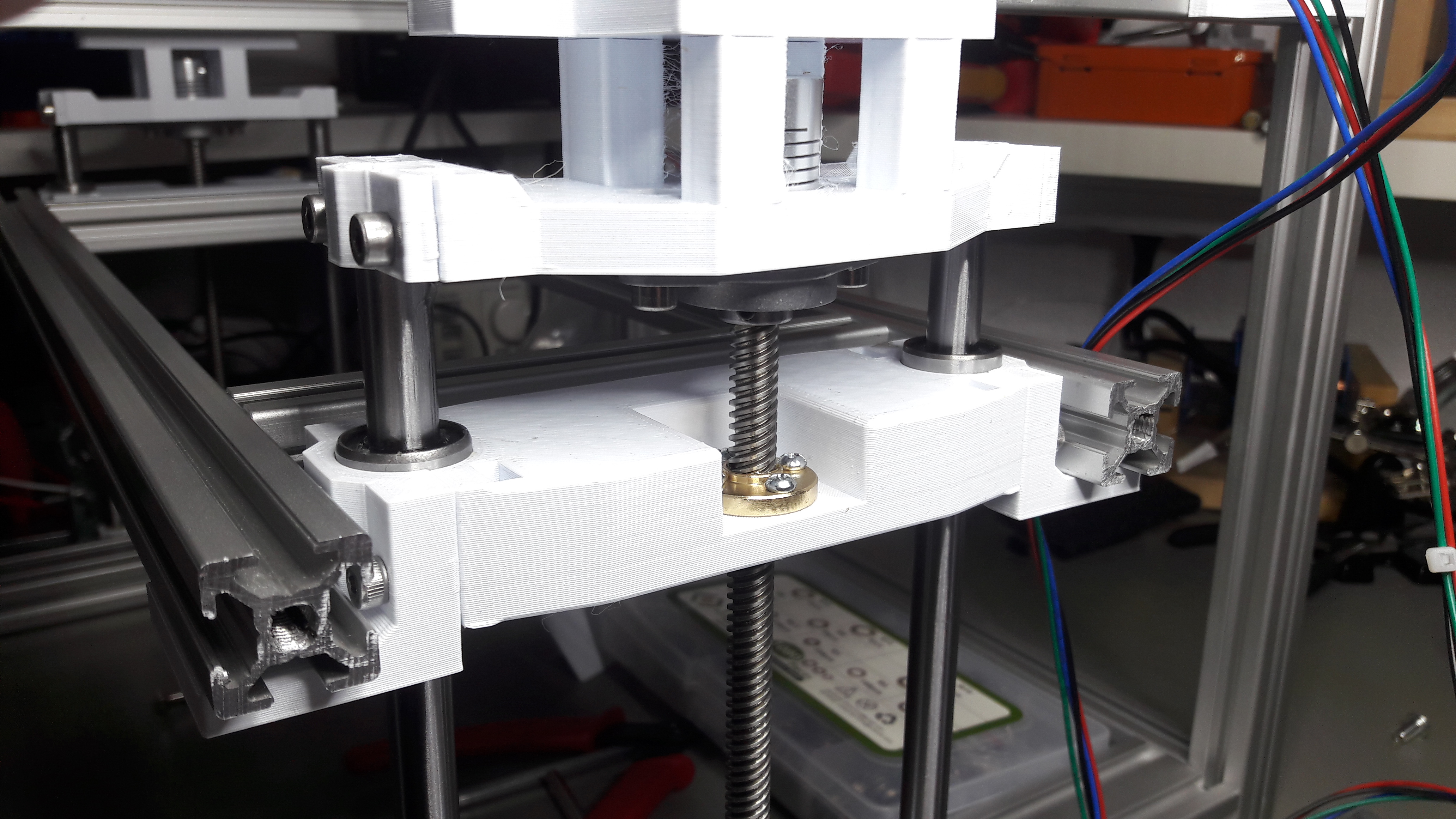
I decided on a new design, which would be much more rigid. The Z nut would be in the same part that holds the LM10UU bearings.

There was still a slight inaccuracy involved in the printed part in the end and the bearings would show still a slight resistance. The source of this slight resistance were probably inaccuracies in the printed part. But they felt not too bad and I continued assembling.
To be sure that the slight binding of the bearings would not affect the print quality later I checked with a dial gauge I got for 11€ from Bohrers.
The final test was with the whole bed gantry assembled.
And this concludes the whole Z gantry design and assembly. Next up on the list is designing the X/Y gantry kinematics and Core X/Y pulley holders.
