WeirdCube 3D Printer - Devlog 5 - Up to the First Print
This WeirdCube 3D Printer article is about the design of the print head, finishing touches and it's first print. I even got a YouTube video showing the full first print.
Fixing The 8mm Rod Mounts
Due to the 8mm rod mounter parts cracking a bit too easily, I decided to revisit the rod mounter parts. The major change is to get rid of one of the screws. Not only does this save one M4 screw and nut, but it also allows for more consistent grip on the rod with less screw tightening. All the screw now needs to do is to close the small gap and apply a little gripping force on the rod. Prior, with two screws, you never saw or knew when you tightened the screws enough. Now it becomes visible by looking at the gap in the part.
I also started printing PETG without or with only very low fan speed now (10-15%), instead of the 40% fan speed I printed the white PETG parts with. This should also suffice to increase layer adhesion and fix a lot of the cracking problems I faced.
Unfortunately the bridging with PETG suffers quite a bit if you don't cool the part anymore. But the holes in the parts were still round enough to fit the screws and functionality is still more important.
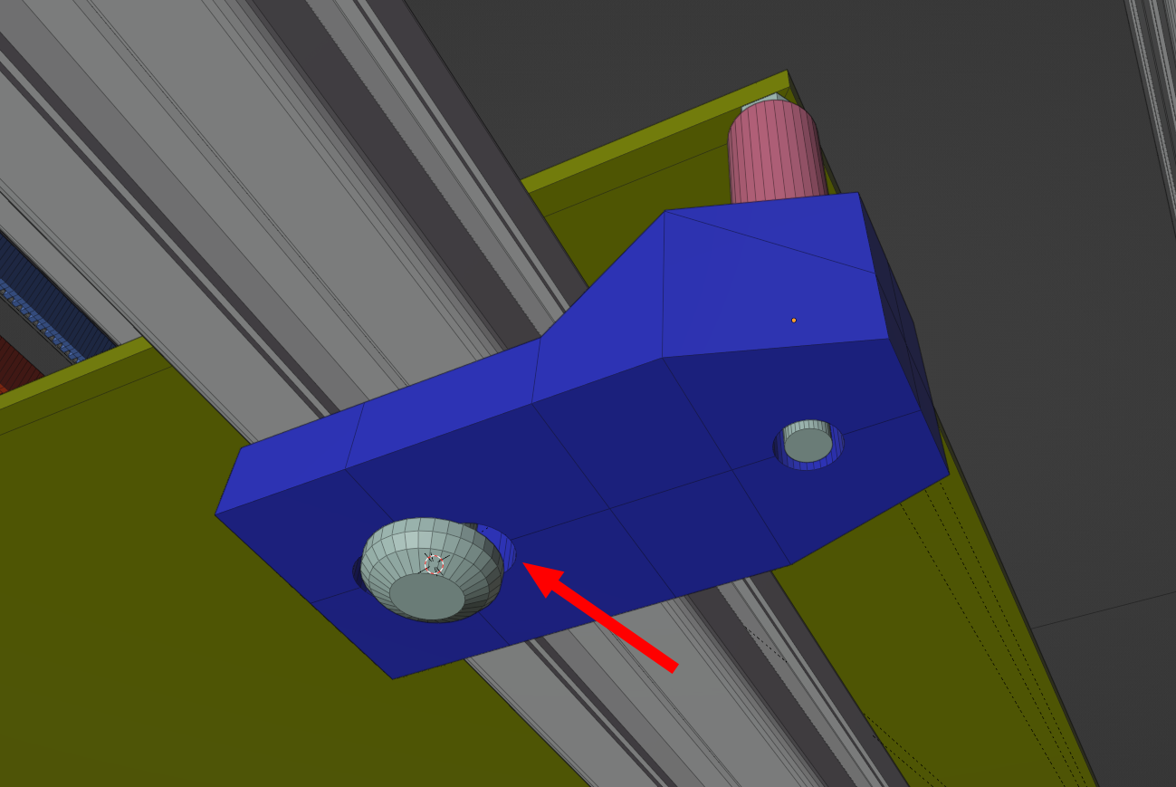
This leads us to the first redesigned rod mount:
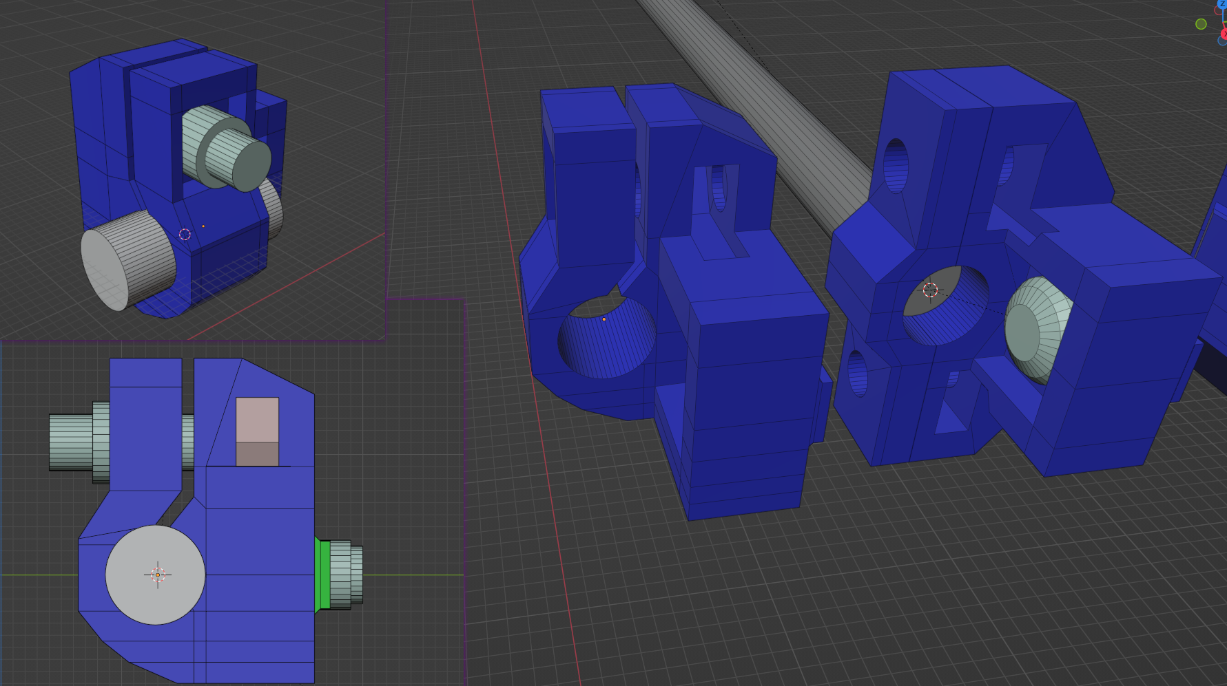
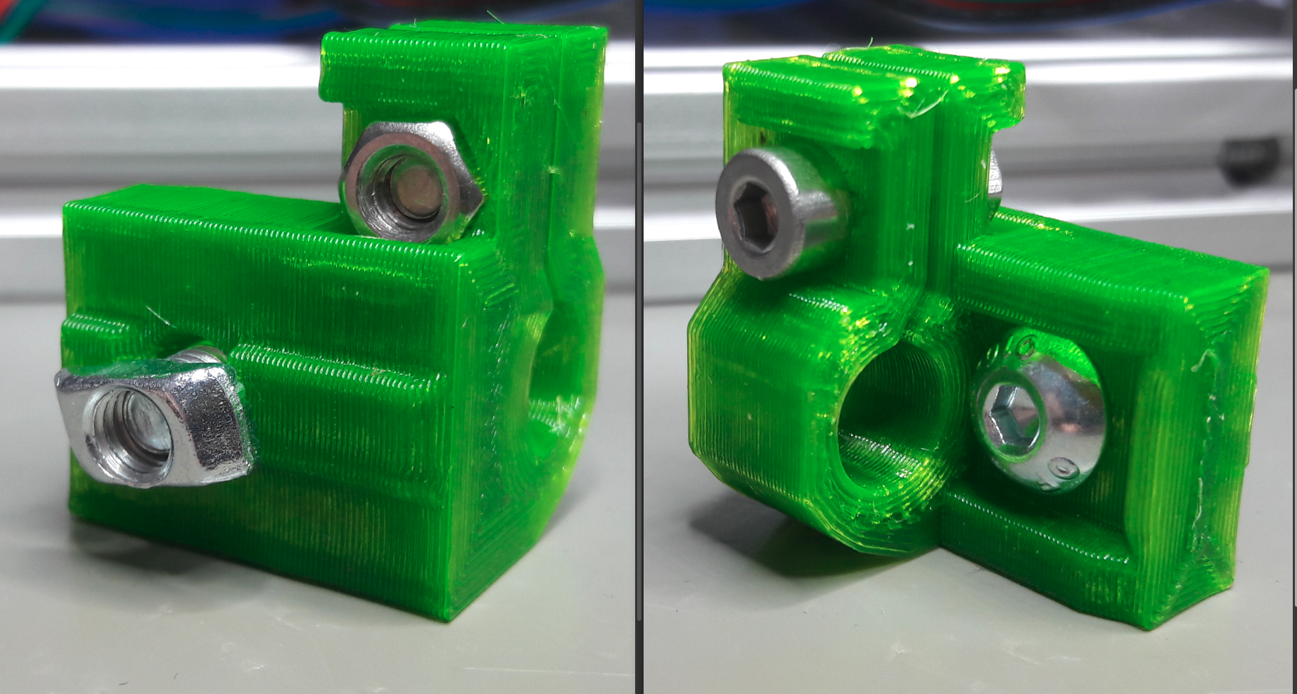
The part became smaller but a bit more complicated. Unfortunately the disabled fan did not play well with this revision. You see in the next picture that there were troubles with the overhangs. For the M5 screw in the green part I cut it away with some pliers to test the rest of the design.
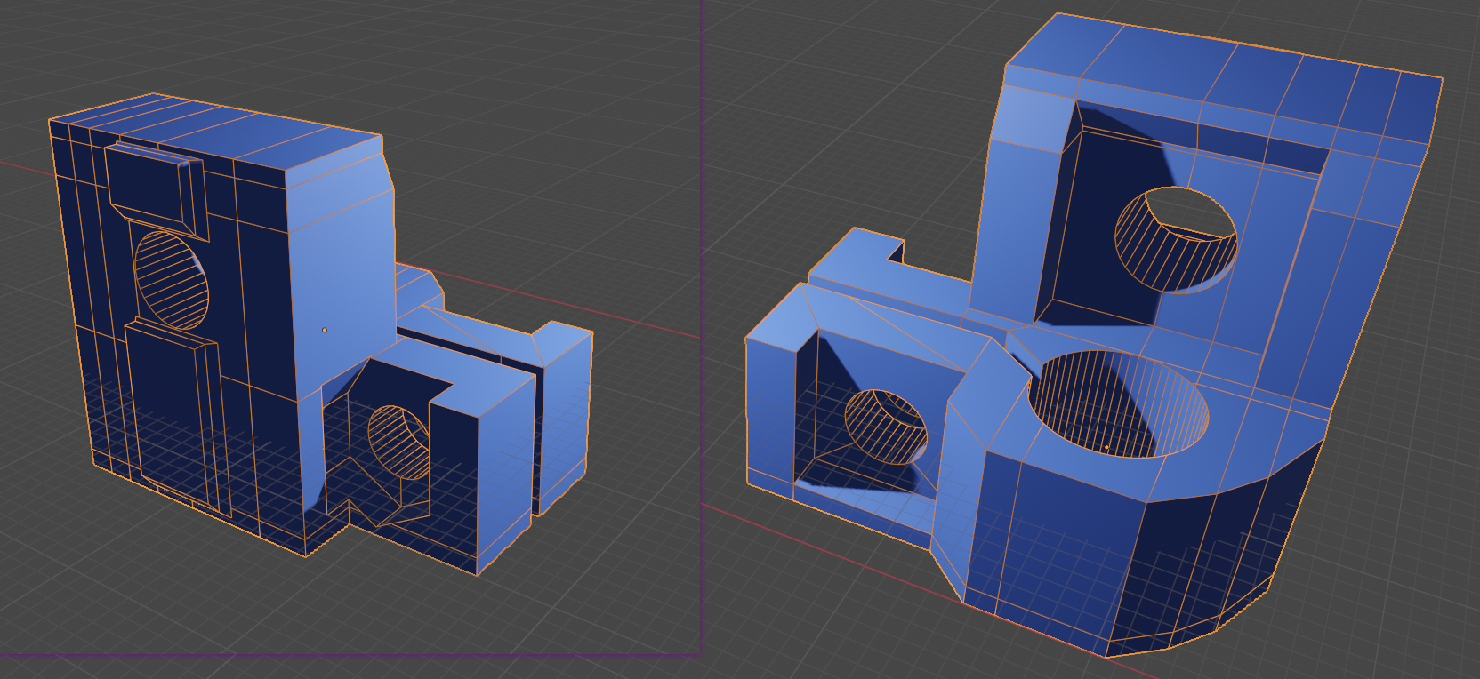
I fixed it by applying a slope to where the overhangs would be.

Unfortunately inserting the M4 nut was troublesome and the overhangs still did not work well. So I completely got rid of the remaining overhangs and reduced the slope even more. Also the nut is now inserted directly into the back. That brings us to the 4th and (for now at least) final revision:
Installing Klipper And Fixing the LCD
I did have problems with Marlin getting the extruder motor to work with the BigtreeTech Octopus mainboard. Even after switching pins around it just would not work in combination with the second (independent) Z axis motor.
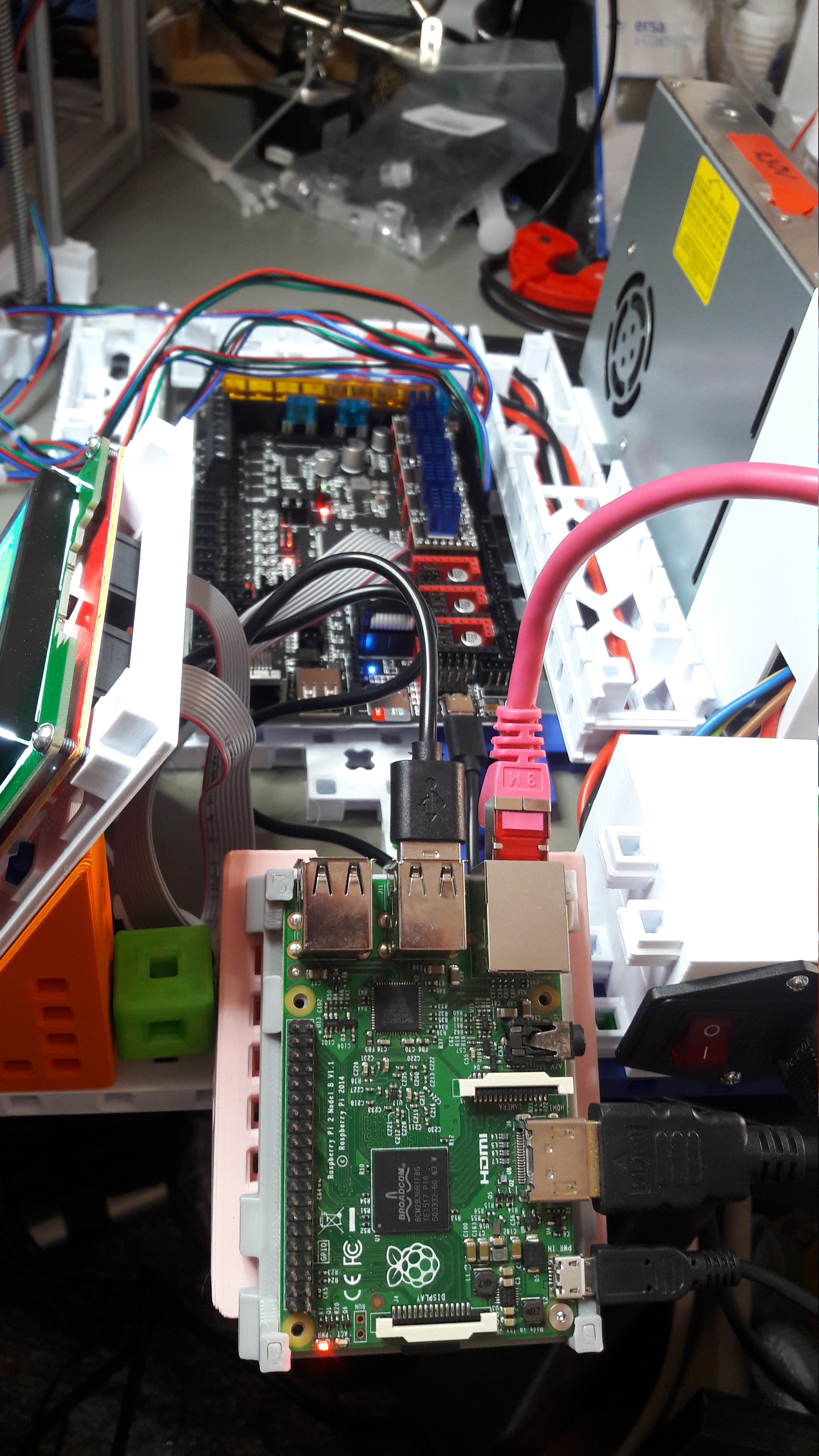
So I dug out an old Raspberry Pi 2 and went down the Klipper route with FluiddPi as base.

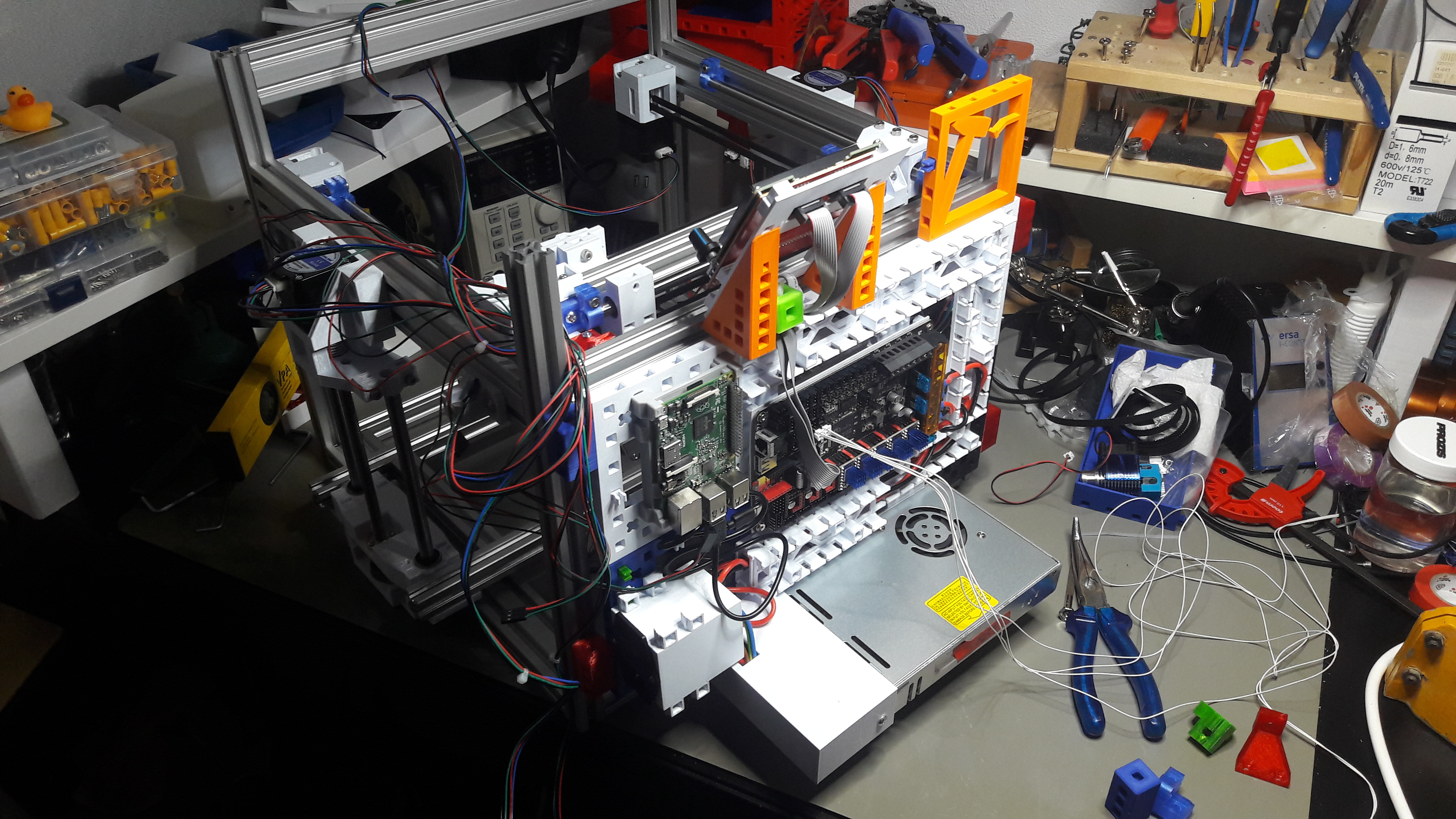
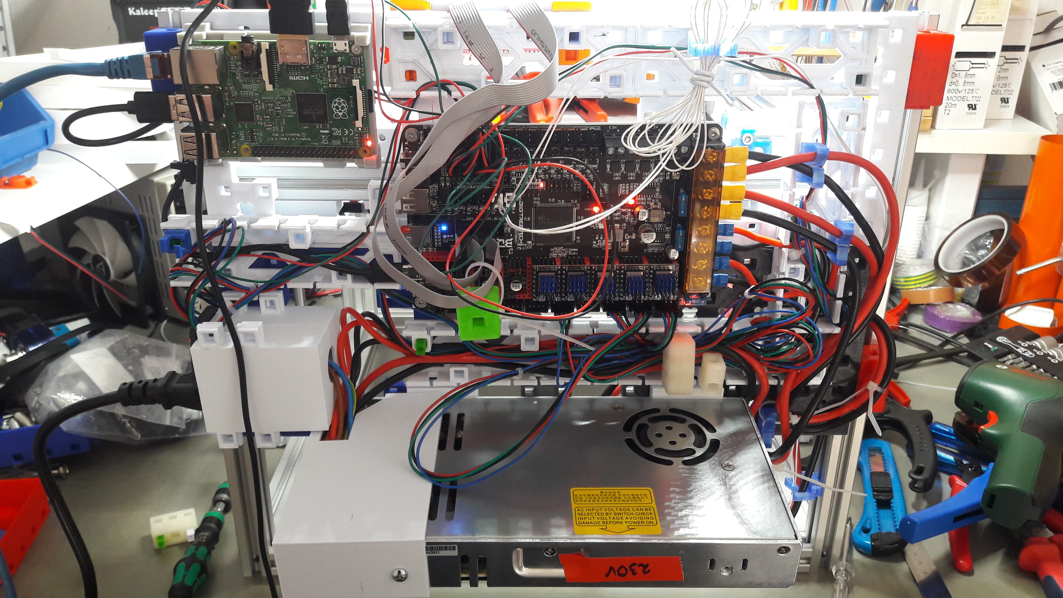
As the mainboard was put on my handy MakerGrid, I could just clip the Raspberry Pi onto the base board:
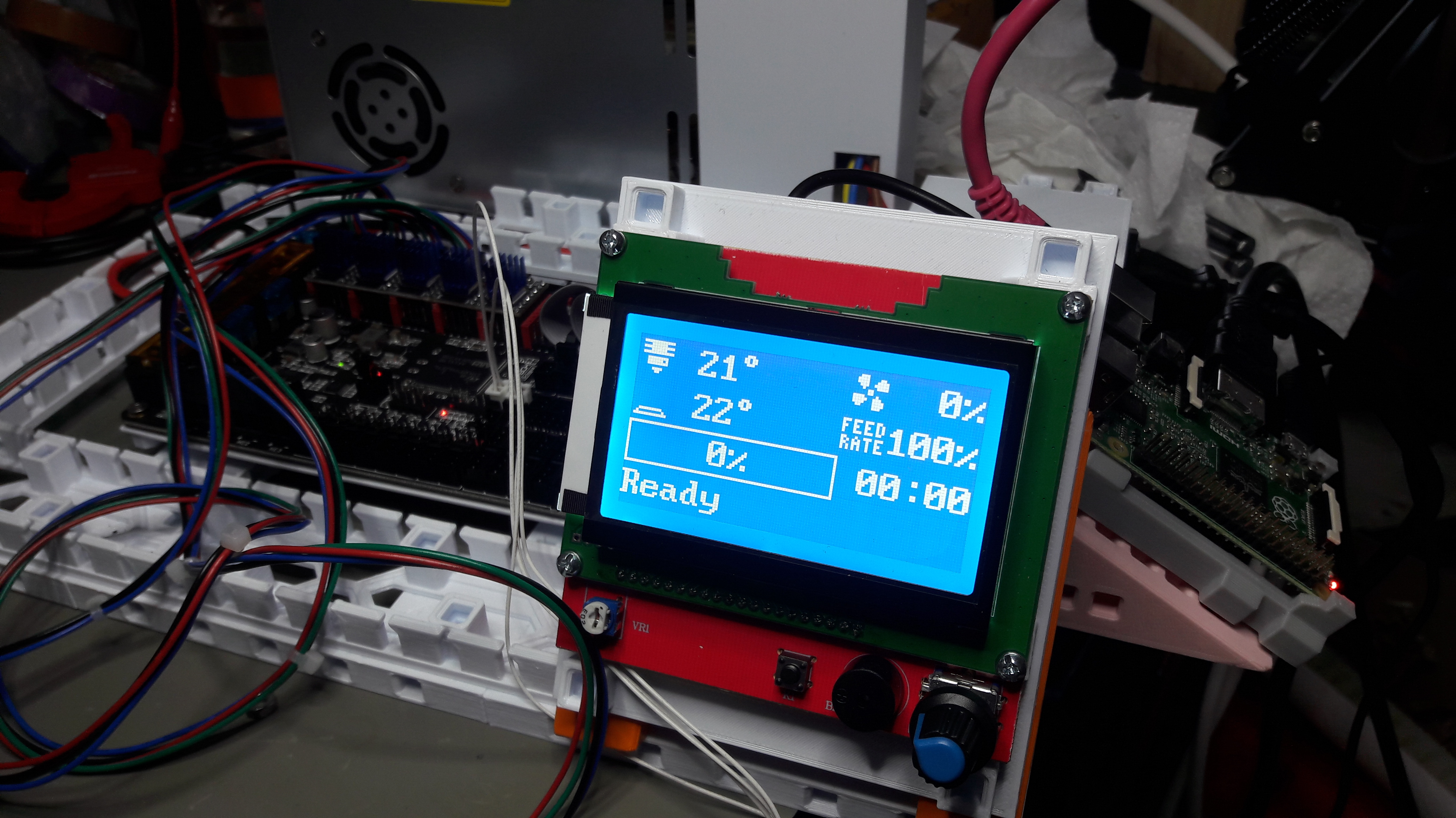
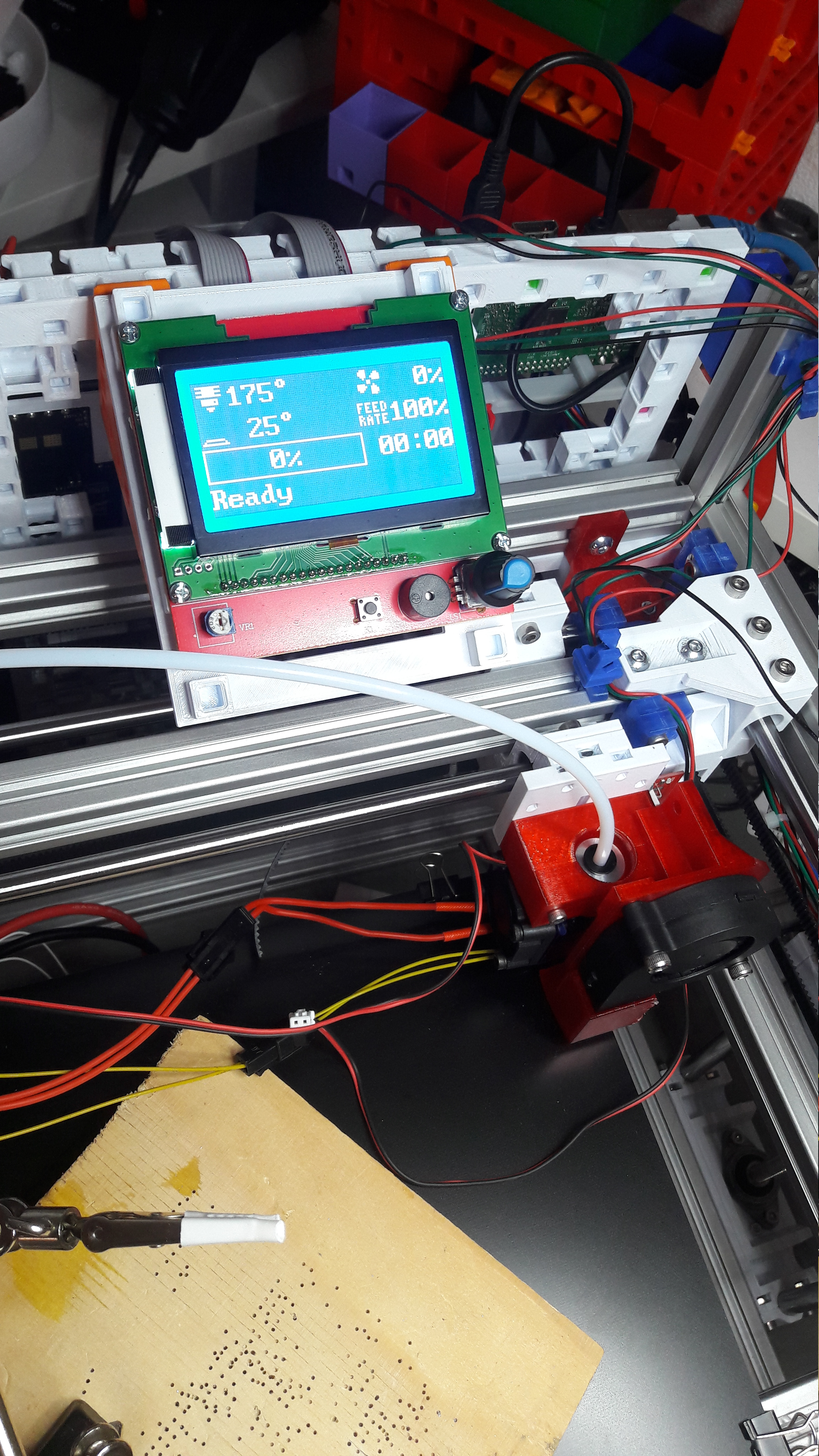
One issue I ran into was, that the cheap RepRap LCD12864 display would not work properly. The whole layout was broken and the font almost seemed to big. It was overall a corrupted output.

Someone hinted me that there is a bug report for that on the Klipper Github: Klipper Github: RepRap Display doesn't work properly #5089. I have no clue why the solution never ended up in the Klipper repository. Maybe because these cheap LCDs are not a target. I don't know. But Stout69 uploaded patched files to his Github: Stout69 - For Klipper.
Now that I patched Klipper it works very fine.
The X, Y And Z Endstops
To get the WeirdCube 3D printer work properly I needed some end stops now. One for the X, one for the Y and also two for the Z axis. Eventually I will install the Trianglelabs 3D Touch I ordered a while ago. But for simplicity and the first prints I will use Z end stops.
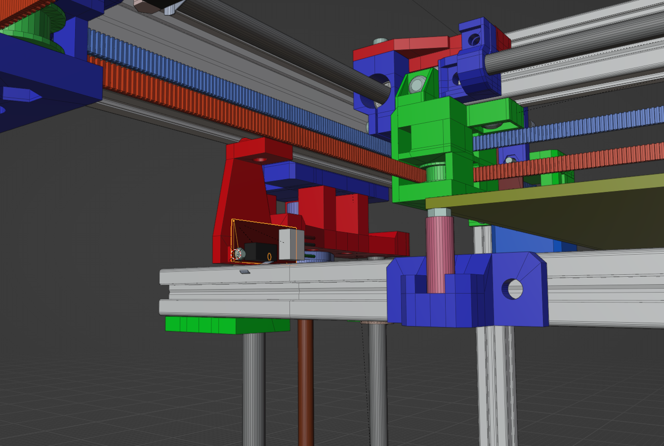
The design for the Y end stop was not complex, I just needed to somehow screw it onto the aluminum profile in the back.

The X end stop was a bit trickier. I needed to find some space to put it and where the print head would properly reach it. I decided to modify one of the X rod mounts to have a holder directly integrated.
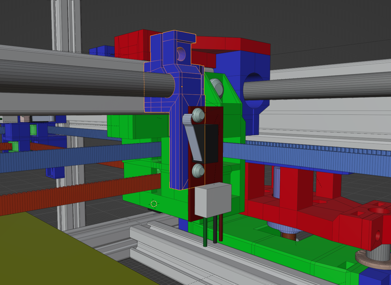
It was quickly printed and this is the result of the first test drive:
The Y end stop was also quickly installed and here you can see the WeirdCube homing it's X and Y axis:
Z end stops would just be a modified Y end stop and be mounted directly to the top Y aluminum profiles.
Two small prints later I got it working. It also would properly auto adjust any Z tilt. Eventually this will be done with the bed probe. In the following video notice how the Z tilt correction works splendidly!
MakerGrid Backpanel - Making The Printer Portable
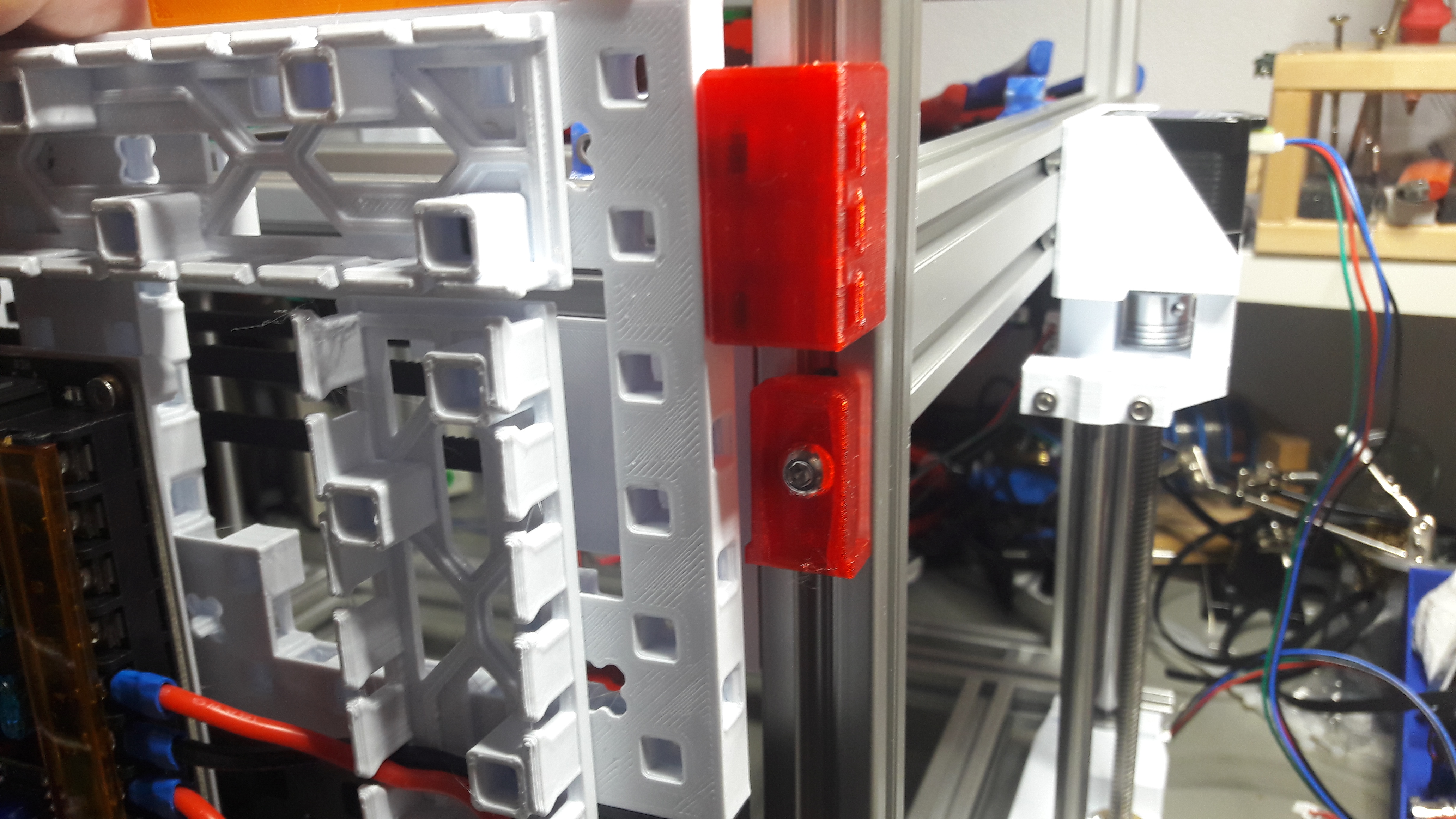
Next step for getting the printer ready for it's first print is mounting the mainboard to it. Lucky and mostly by coincidence I built the frame to be 360mm wide. That allows me to fit the MakerGrid panel perfectly to it's back.
I quickly designed dovetail mounts for the 20x20 profiles and have the corresponding MakerGrid build cube slide over them.
You can find the models in the MakerGrid repository:
- m5_dovetail_mount-mount_with_t_slot_align.stl
- m4_dovetail_mount-side_clip.stl (Ignore the m4 in the file name, it's working for the M5 dovetail mount too)
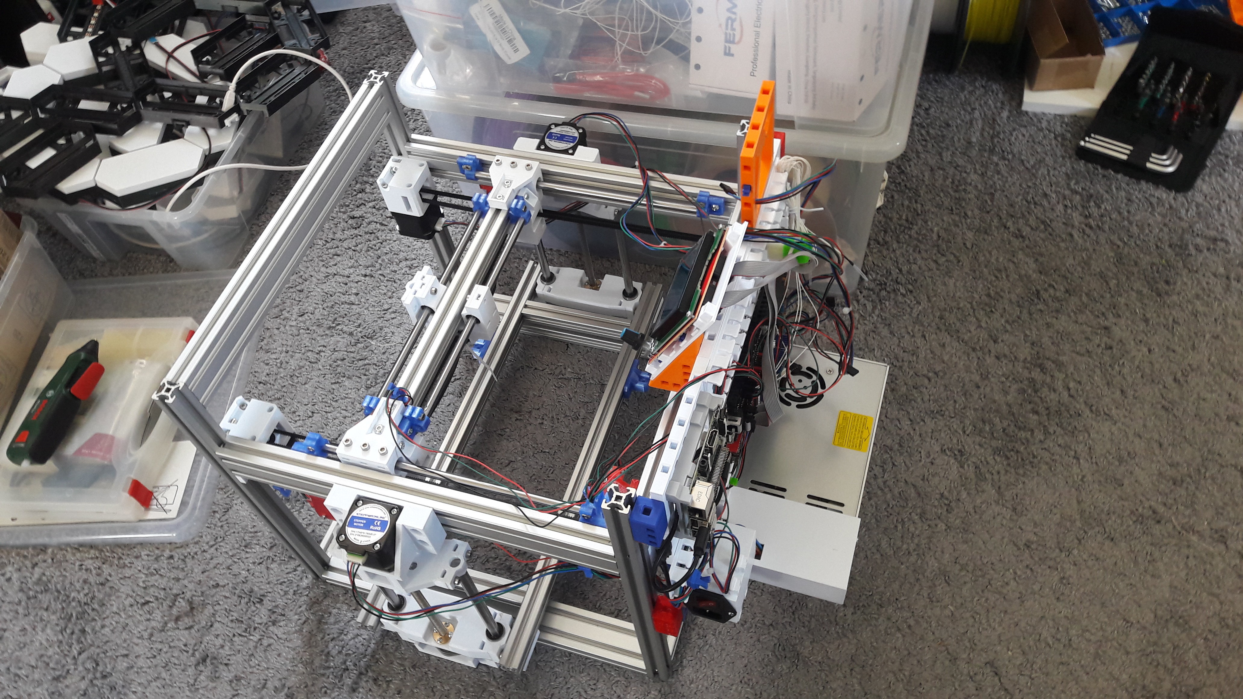
The finished result looks very promising:
I needed a clean workbench for one of the next steps. And now I could finally lift the printer off my workbench and put it temporarily somewhere else.
MakerGrid Compatible Cable Management
I also needed a solution for managing the hanging cables on the printer. For this I invented a MakerGrid clip that can be put directly into the T-slot aluminum profile (with 6mm gap). And also a cable holder/clip that can be plugged into any MakerGrid clip.

Here is a quick demonstration of how it works:
I recommend printing this from PETG, as it has been designed to press tightly into the T-slot profiles. You can find the models here:
Preparing the MK3 Heated Bed
The MK3 heated bed needed to be mounted onto it's gantry. For this I first needed to prepare it and drill proper sink holes for the M3 screws. For this I needed the clean workbench I mentioned earlier.
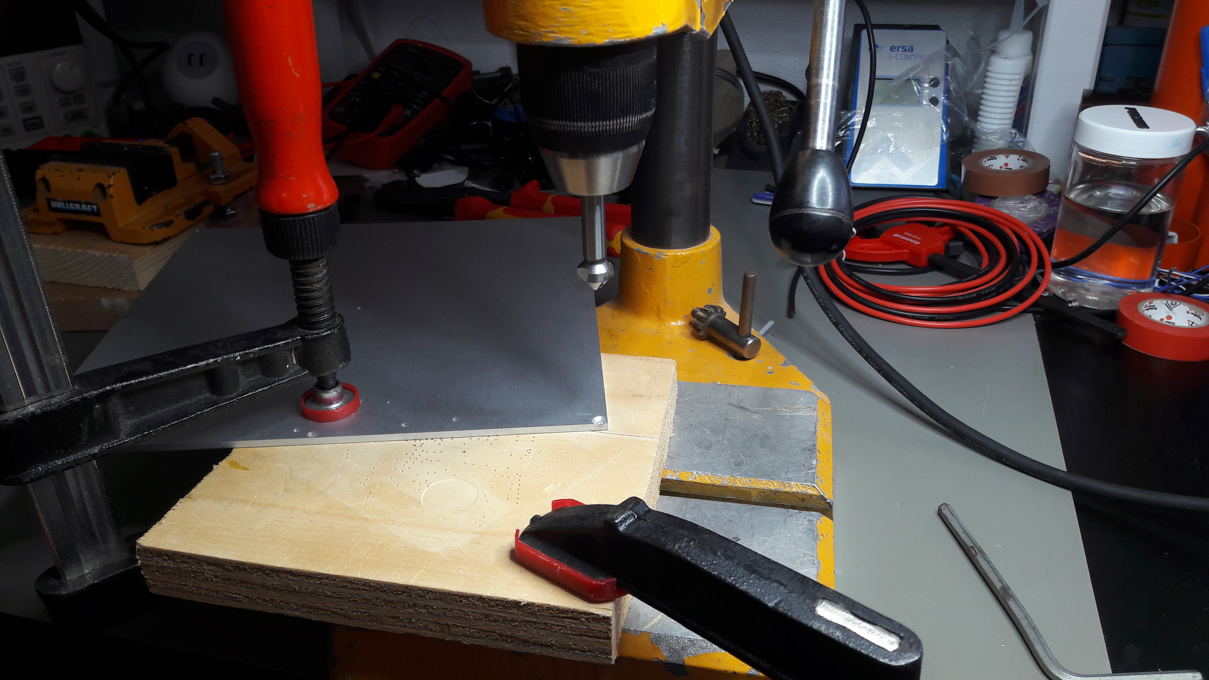
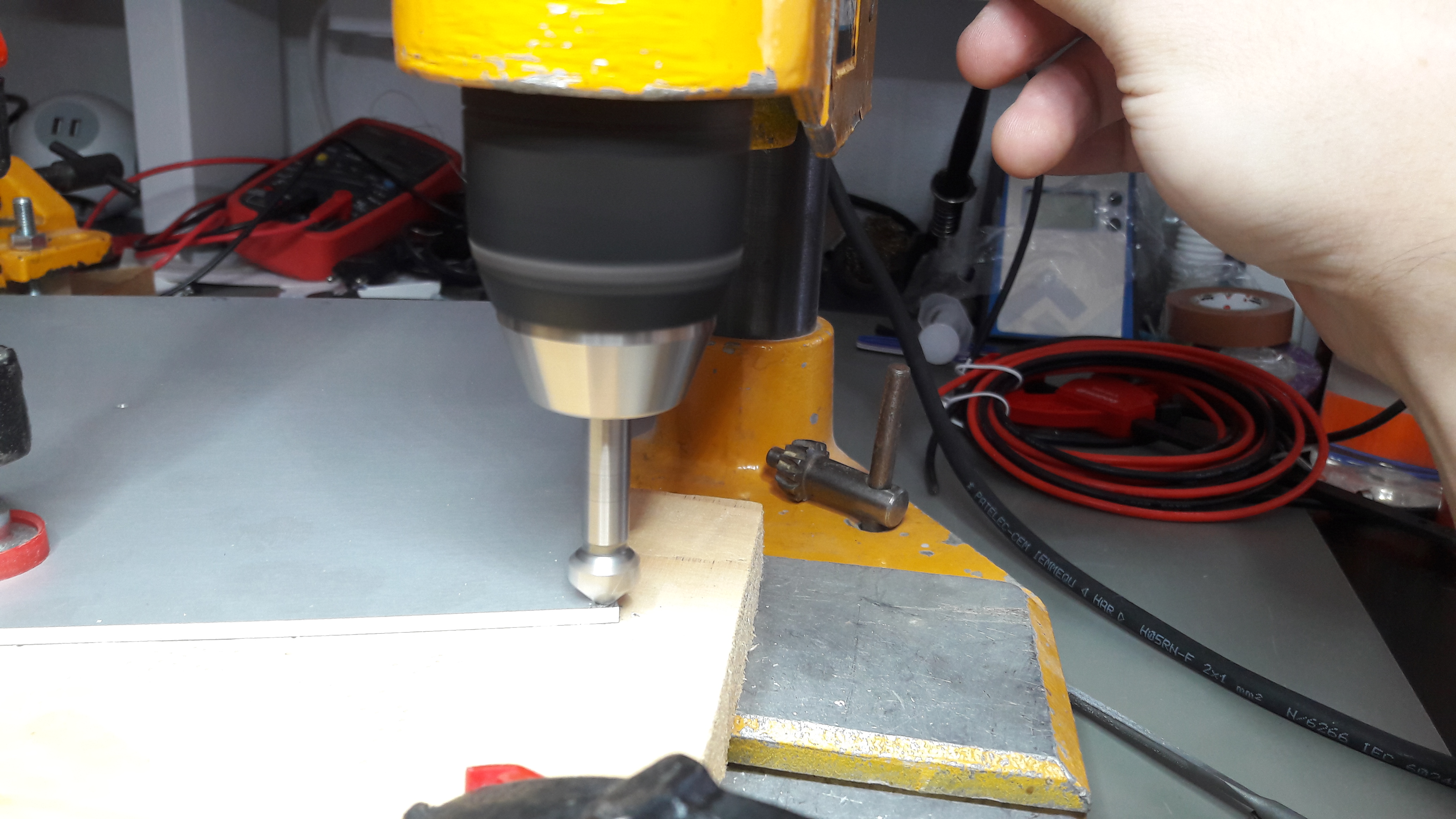
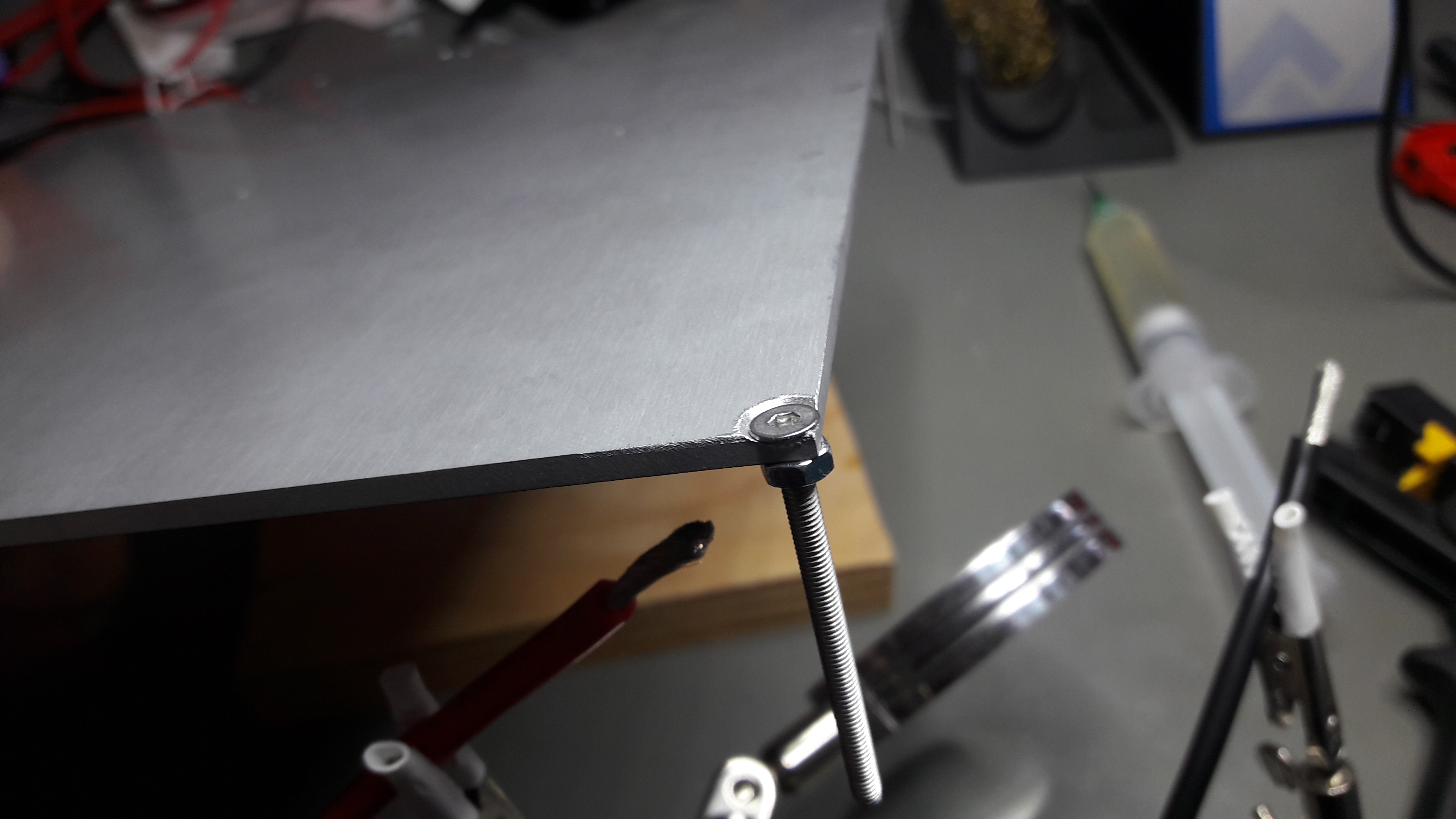
The boring was a bit of a challenge, mostly because I could not properly center the 45° angled sink drill bit to the holes. But it worked out in the end.
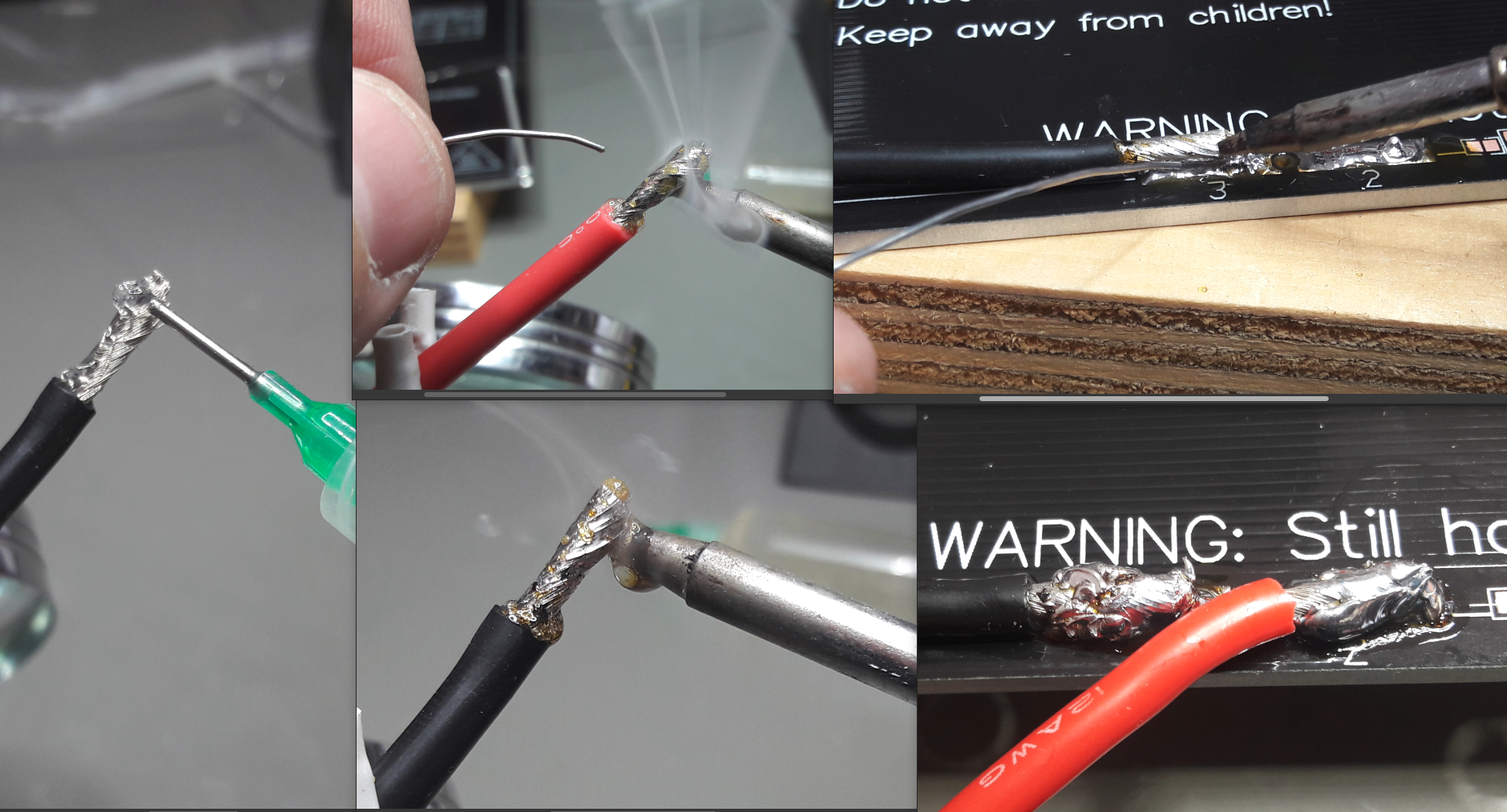
Soldering the cables was also a challenge, mostly because they were very thick and the soldering iron I used did almost not have enough power. The aluminum heat bed sucked away so much energy later that the soldering iron almost got stuck on it. But the heat bed worked very well in the end.
For the bed gantry I redesigned the screw mounts to be adjustable. Mostly because the screws were not perfectly straight in the sink holes and second because the gantry width itself was off by about 0.5mm, so that the previous rigid holders would not fit perfectly.
A few prints of these later I was able to mount the MK3 heat bed to it's gantry:
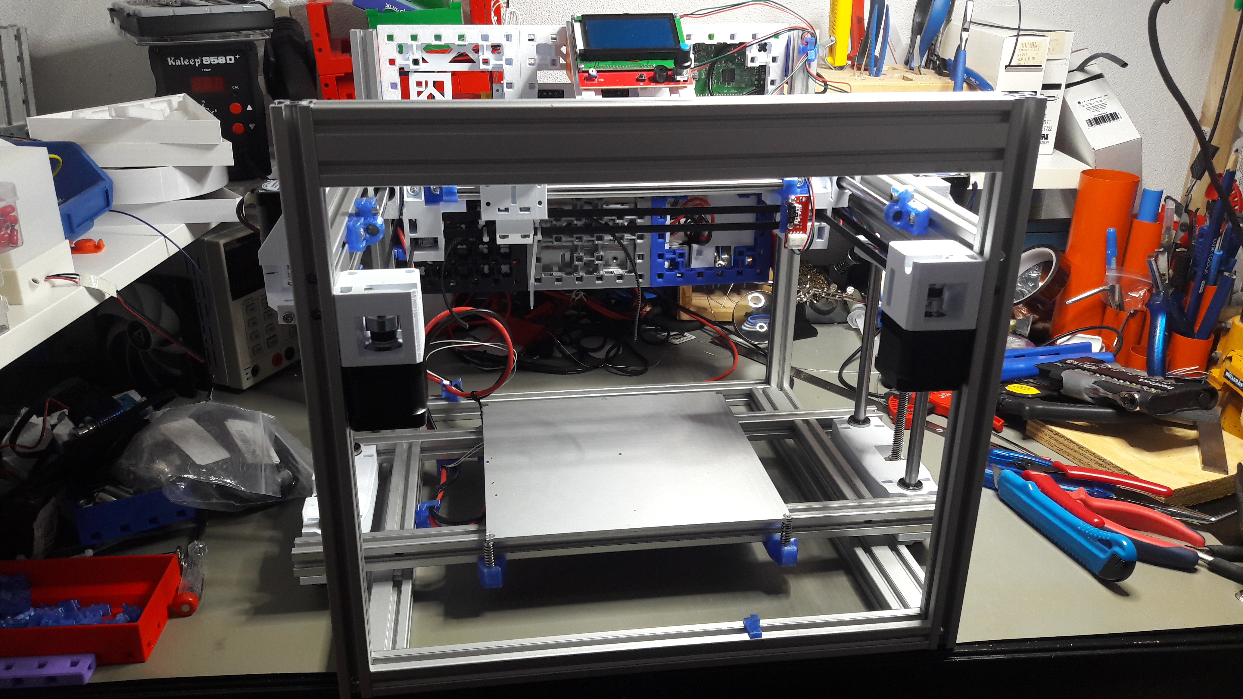
The new cable management clips worked out nicely to hold the bed wiring:
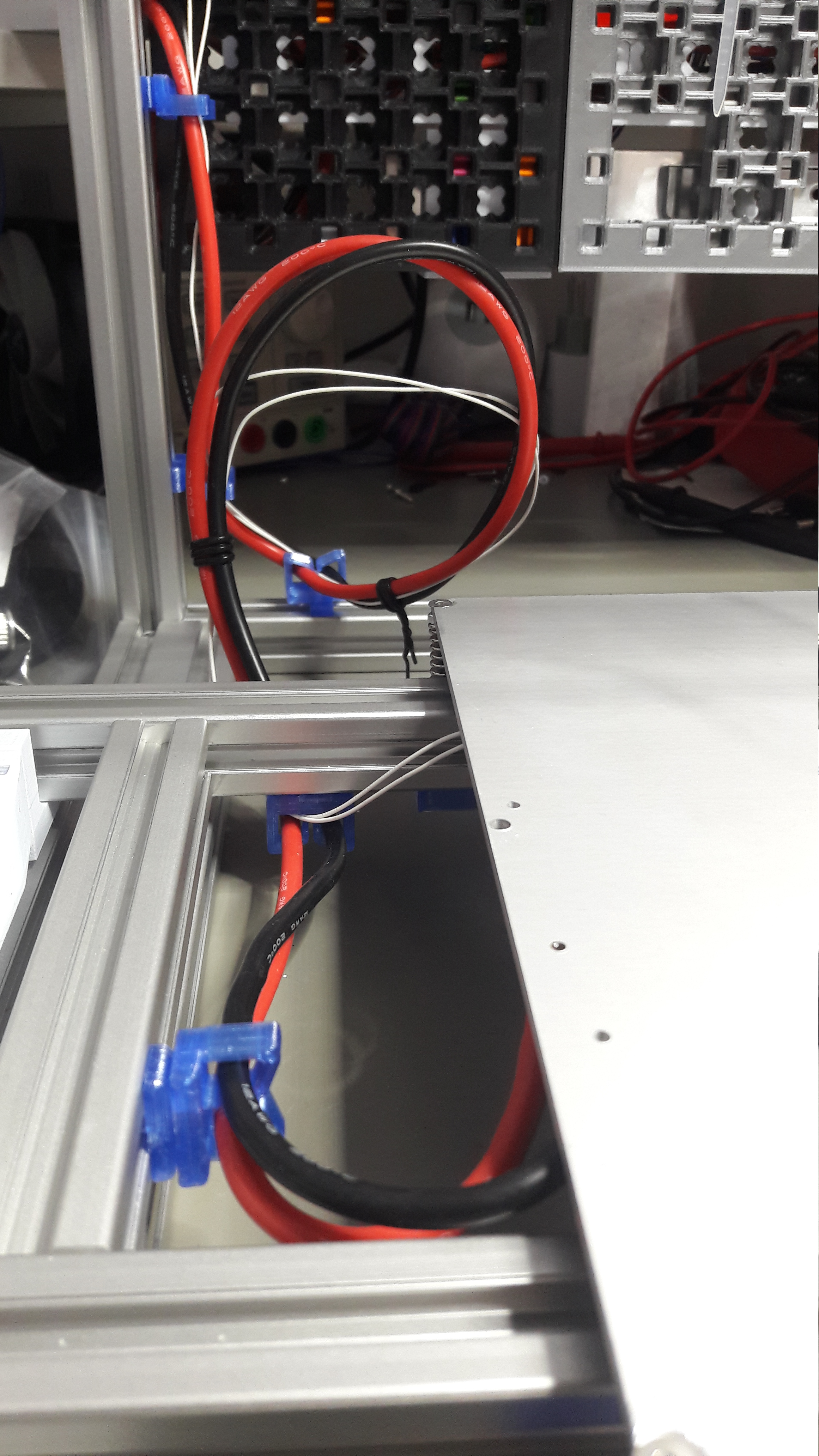
Next thing was wiring the bed up to the mainboard. Notice the 4 thick red and black wires on the top right. The bed cables need to carry lots of power and should not heat up, so I used some extra thick wires.
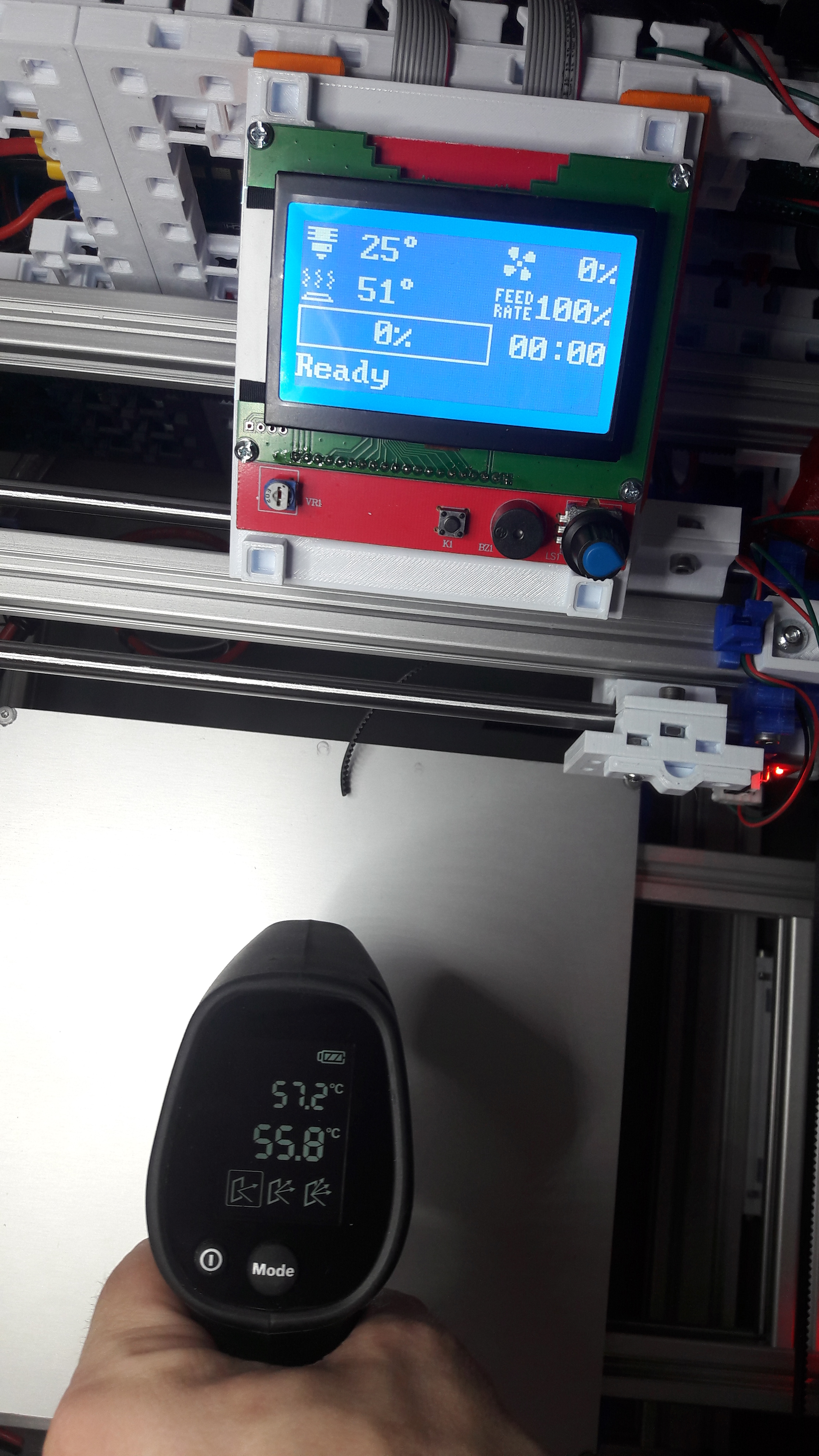
The test of the circuit wiring worked on first try. The temperature was off by about 5°C, but I'm used to that from my other printers. That just means I will have to print at 55°C to get an actual temperature of 60°C.
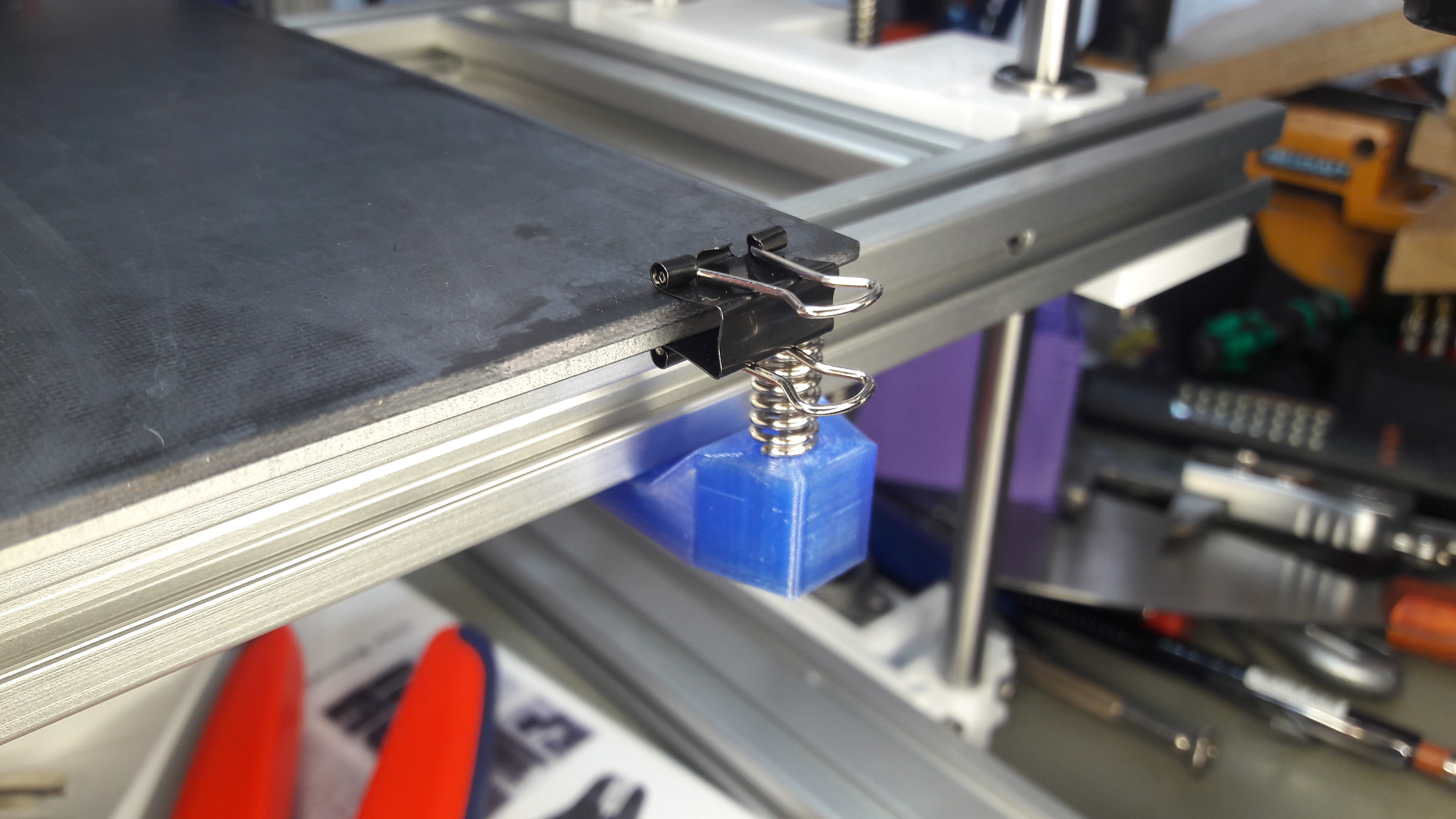
I do not show how I prepared the GFK/FR4 print platform in detail. It suffices to say that I ground it well with some 400-800 sand paper to get a matte surface. It holds onto the MK3 heat bed with some paper clips.
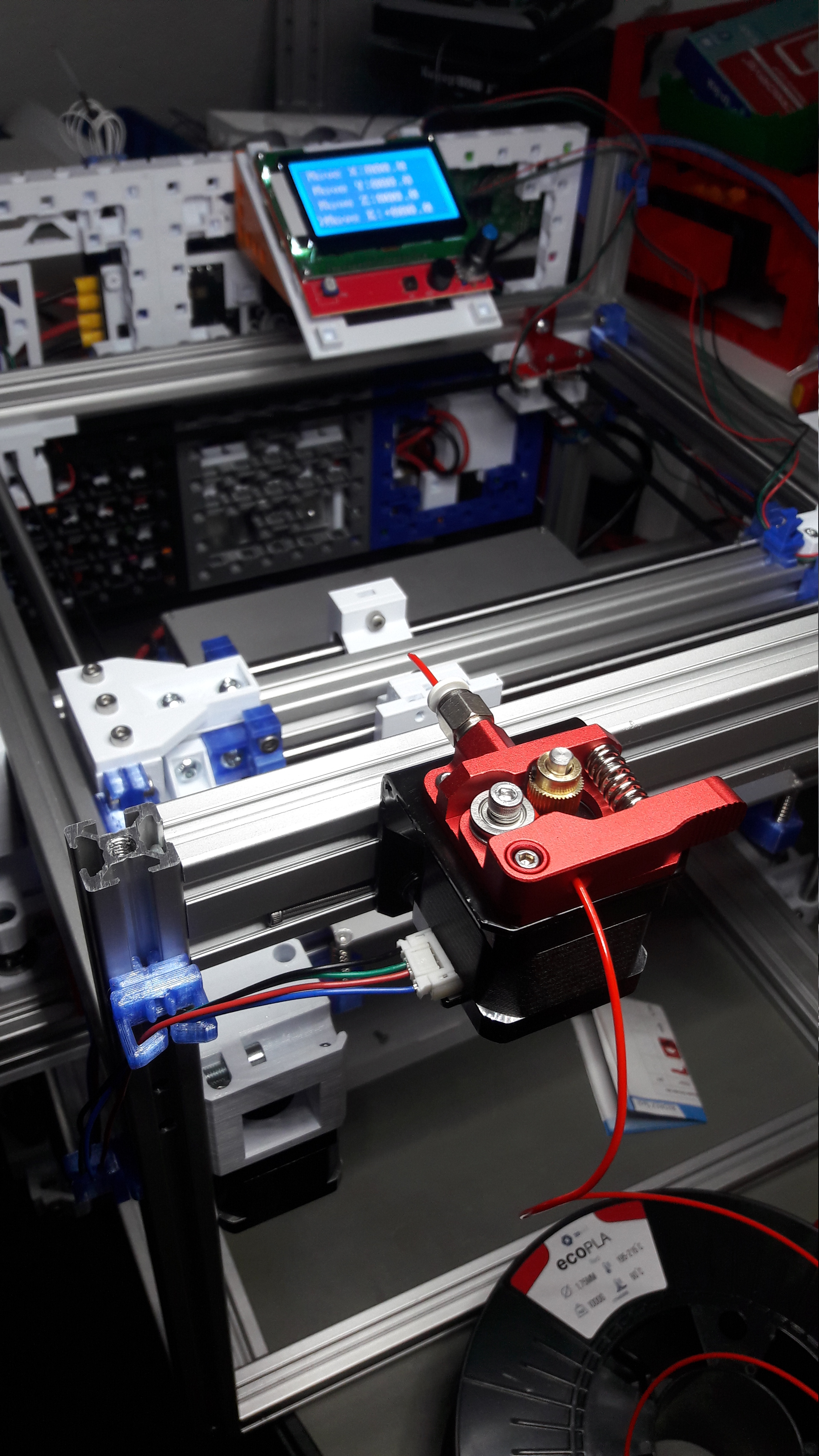
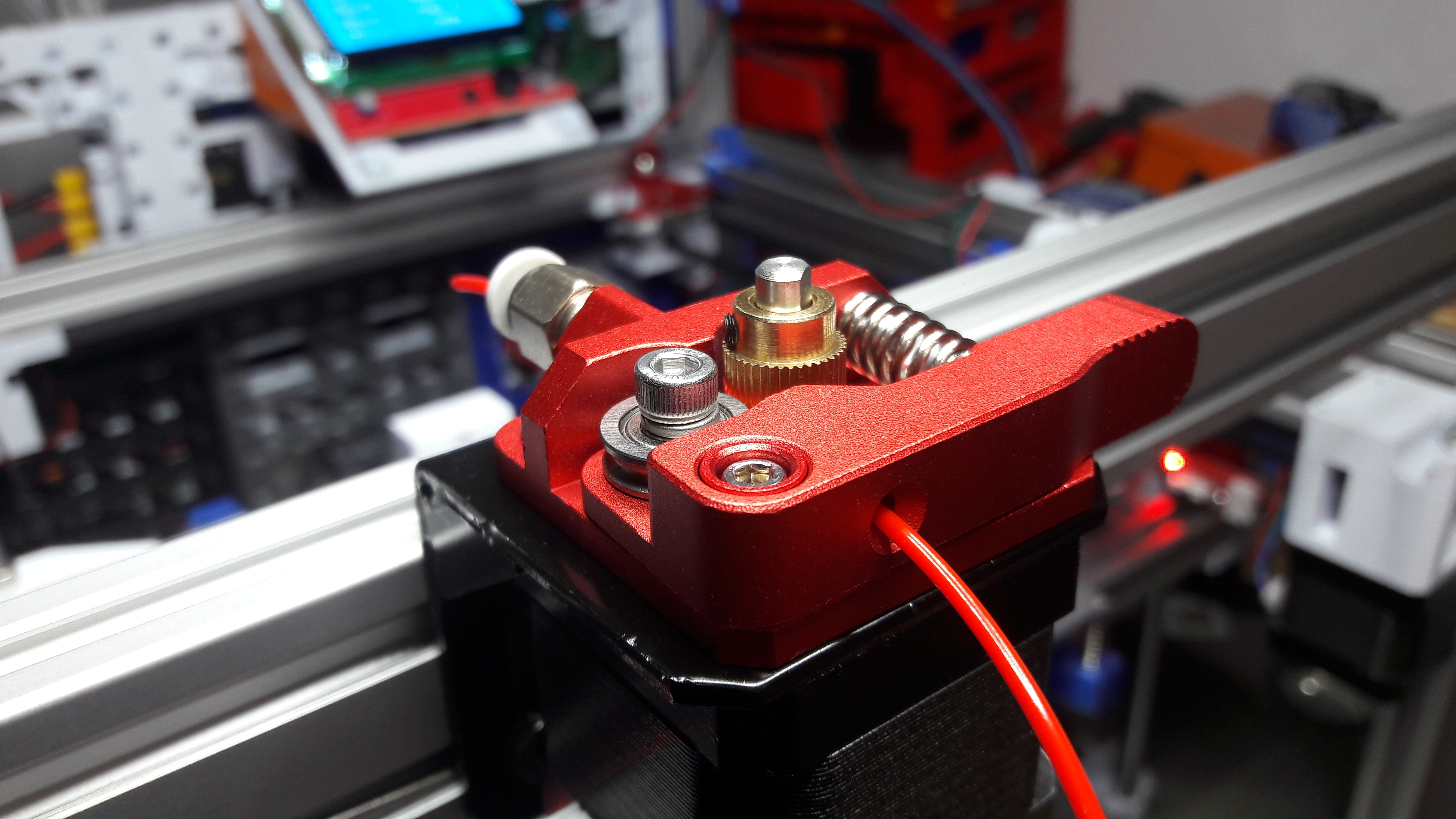
Extruder, Hotend and Print Head
Every FFF (FDM) 3D printer needs something to push the filament. And so does the WeirdCube. I got a spare MK8 extruder in my big box of 3D printing spare parts, which I decided to give a go now. I used the bracket that came with it to mount it to the frame more or less crudely.
For the first prints I wanted to go with a Bowden style extruder. Even though I want to try out direct drive with the WeirdCube eventually.
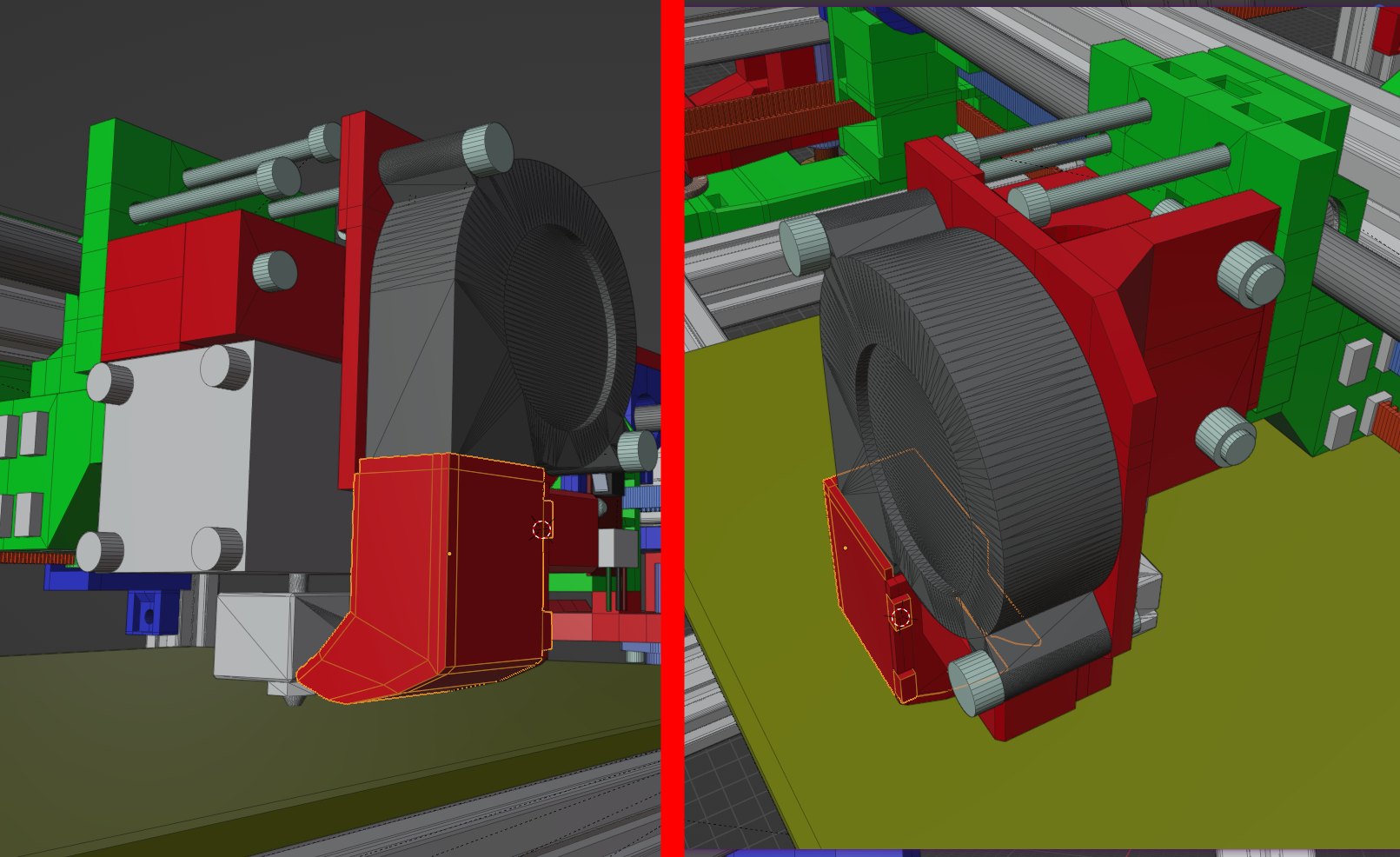
The WeirdCube is still missing it's most important part: The print head! I sat down and quickly sketched up a very basic V6 J-Head hotend mount. The origin of the fan mount and fan duct is the recent Kingroon KP3S upgrade I did. I copied it over and modified it to fit the new height. I also modified the fan duct to be printed in two parts, so I could get away without printing supports.
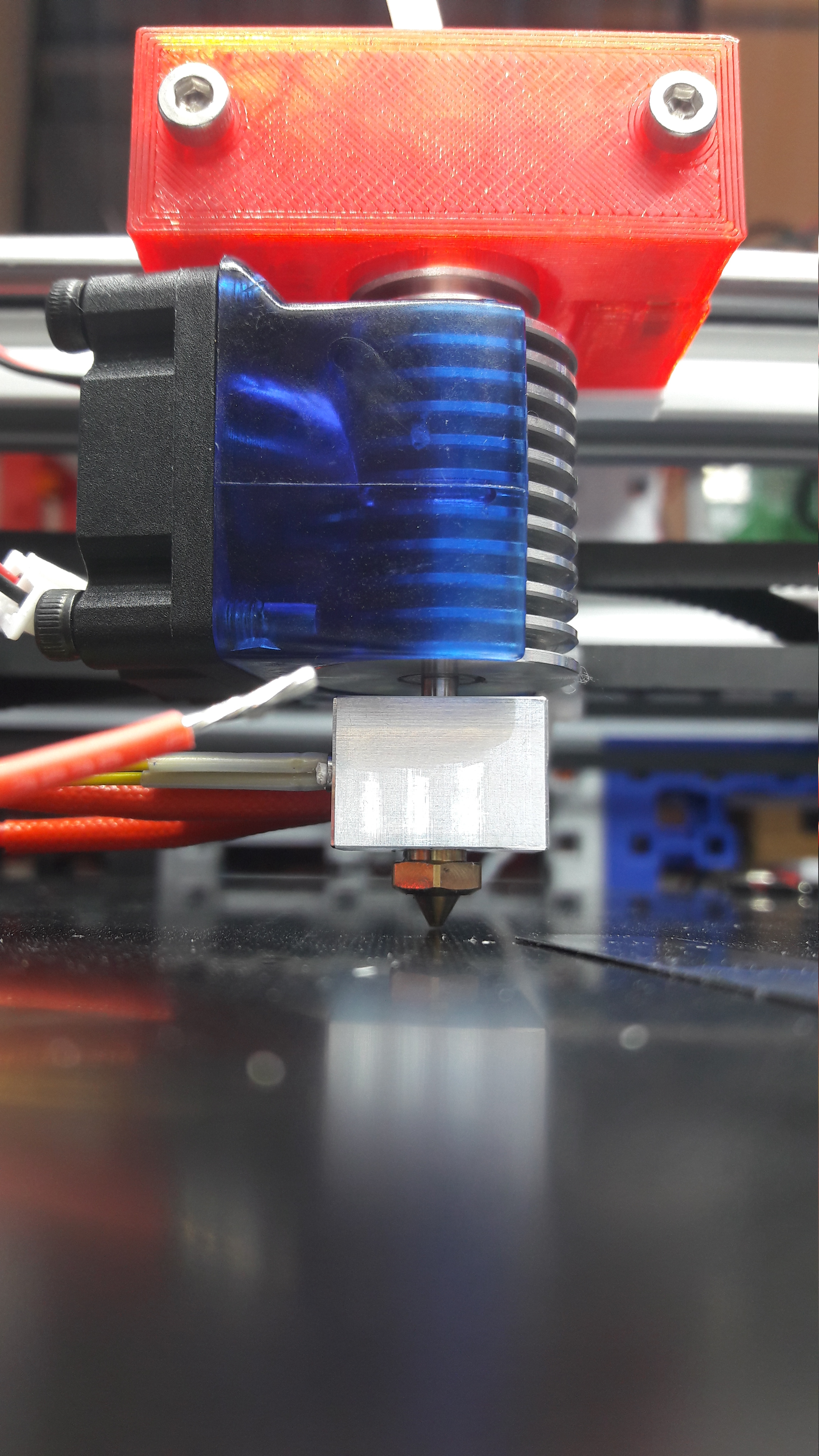
The parts were printed out quickly and I was able to mount the Mellow V6 full metal hotend.
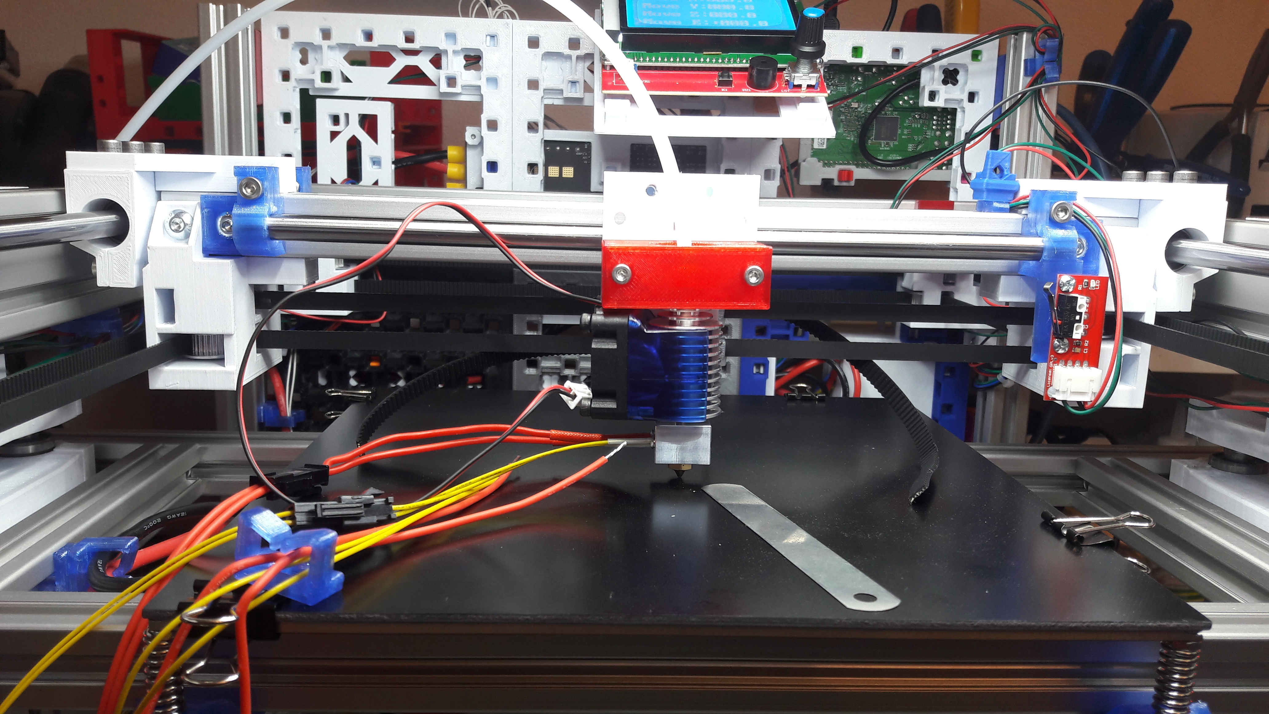
While I was at it, I leveled the bed for the first time.
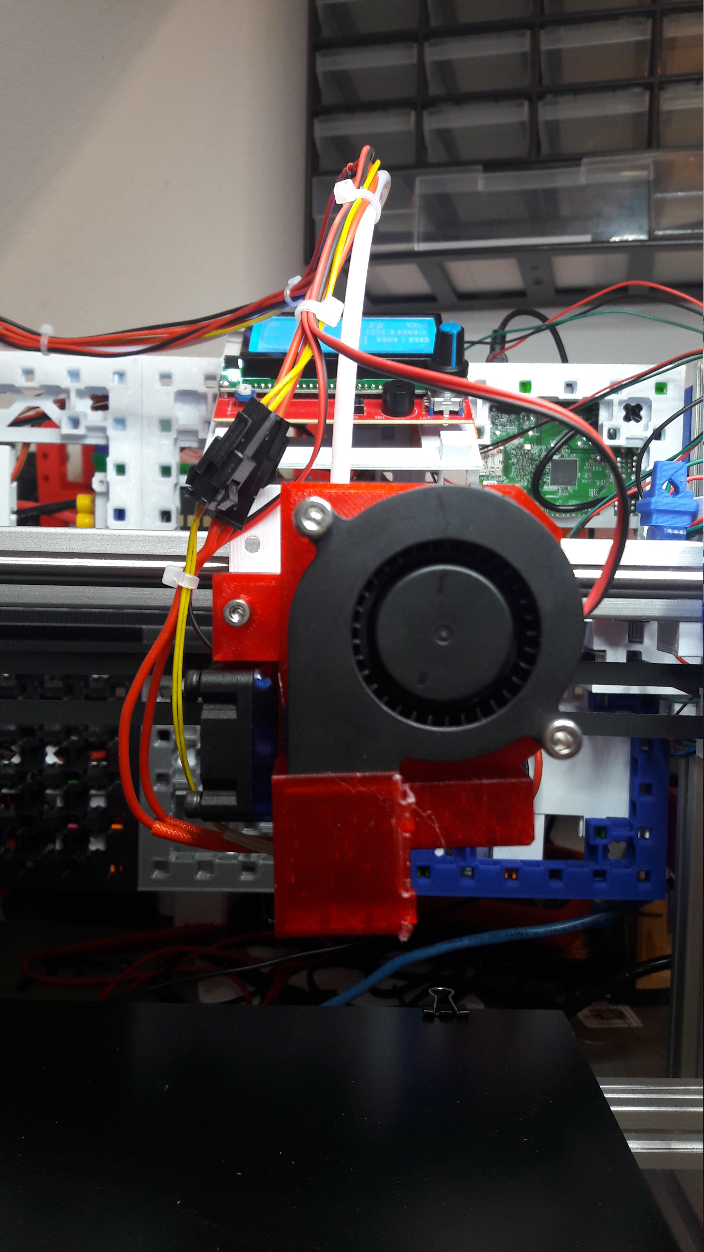
Next I printed the fan mount and fan duct. Yes, the fan duct is glued with some hot glue! The electrical wiring was also quickly done, I was very motivated to finally do my first print with the WeirdCube.

Some of the wiring needed to be extended. I chose to solder longer cables to them.

Once the wires were all attached I heated up the hotend the first time. It all worked splendidly. Configuring Klipper was a breeze, as was working with the Bigtreetech Octopus mainboard.
The wires needed some management. So I temporarily bound the wires to the Bowden tube using some zip ties.
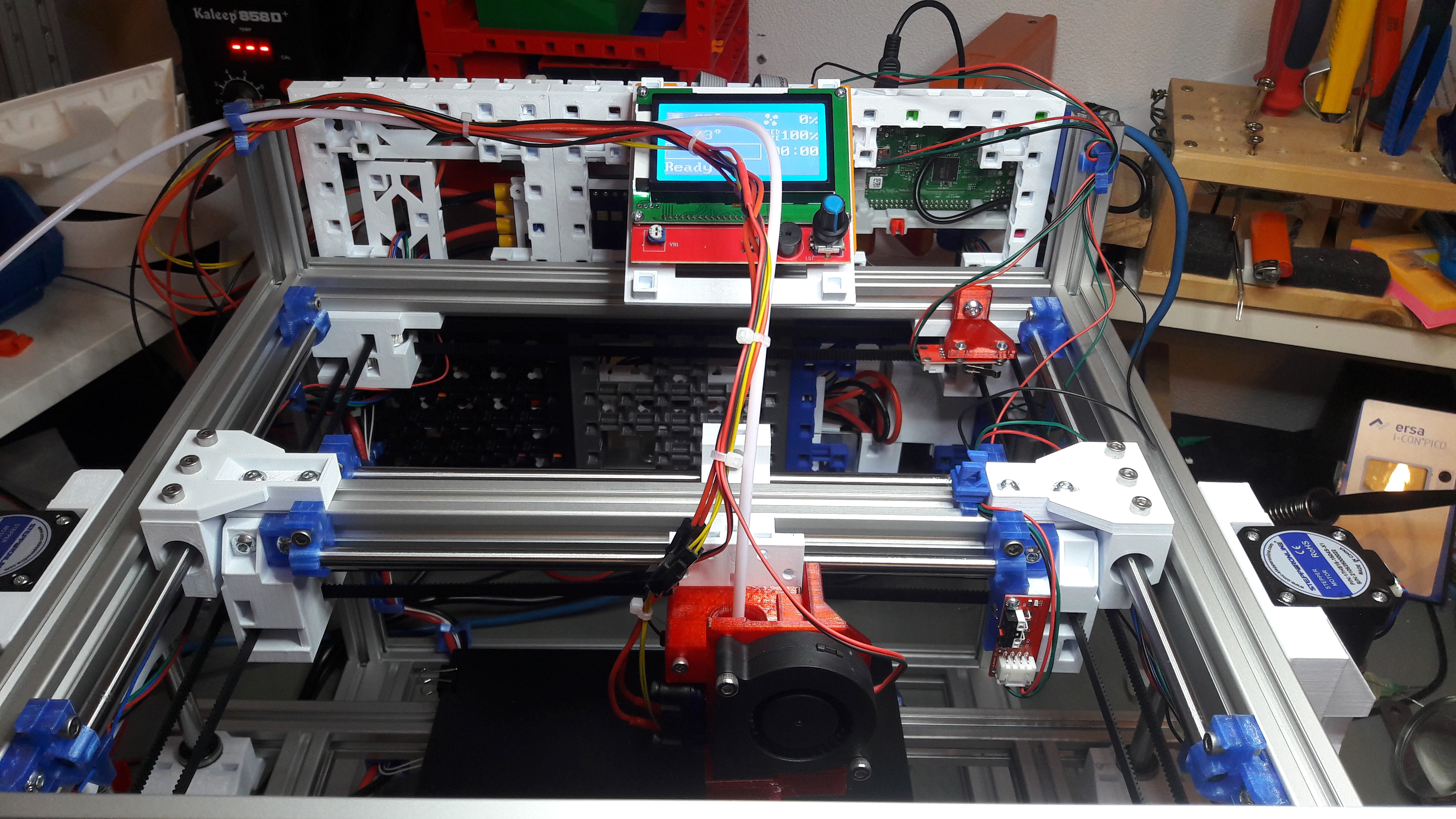
And this concludes the assembly of the WeirdCube. For the first time it was done. All parts were designed, motion system worked, heat bed was mounted and the print head was done. It was ready to print.
The First Print
I setup a WeirdCube printer profile in Cura with some guessed settings and sliced a simple calibration cube model. Loaded up the gcode into Klipper and gave it a go. I was excited and recoded the very first print. Here you can watch it on Youtube:
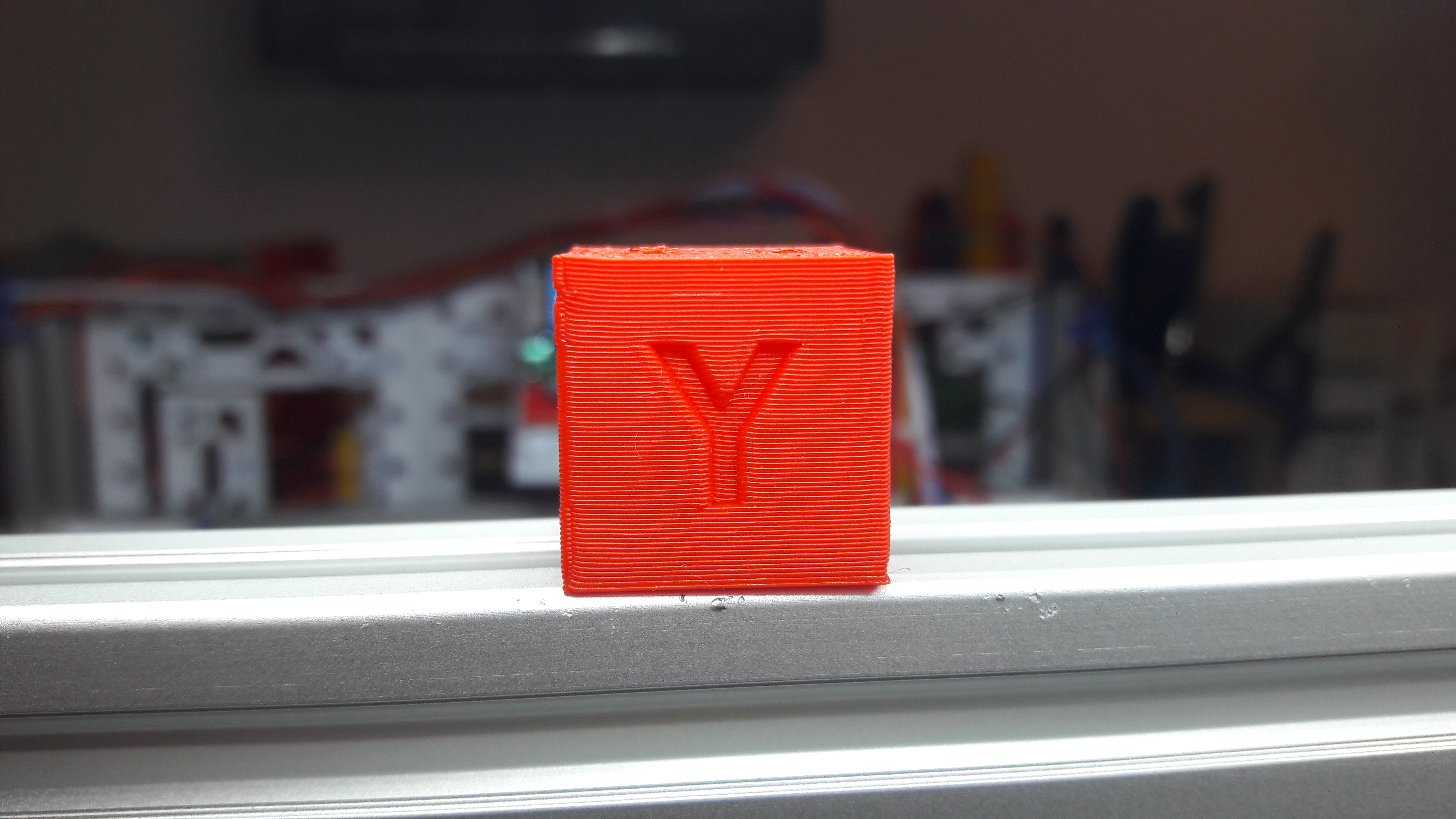
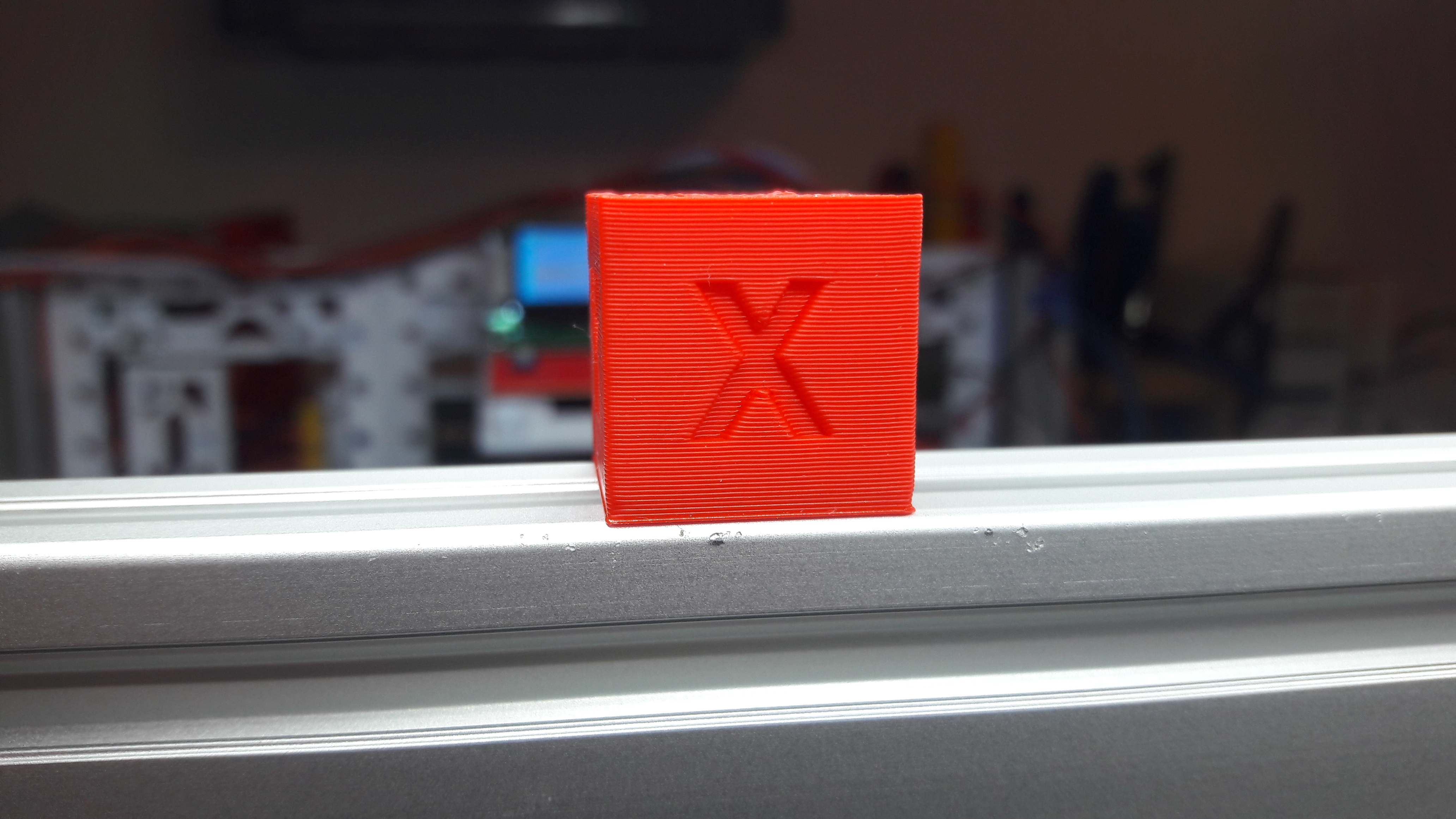
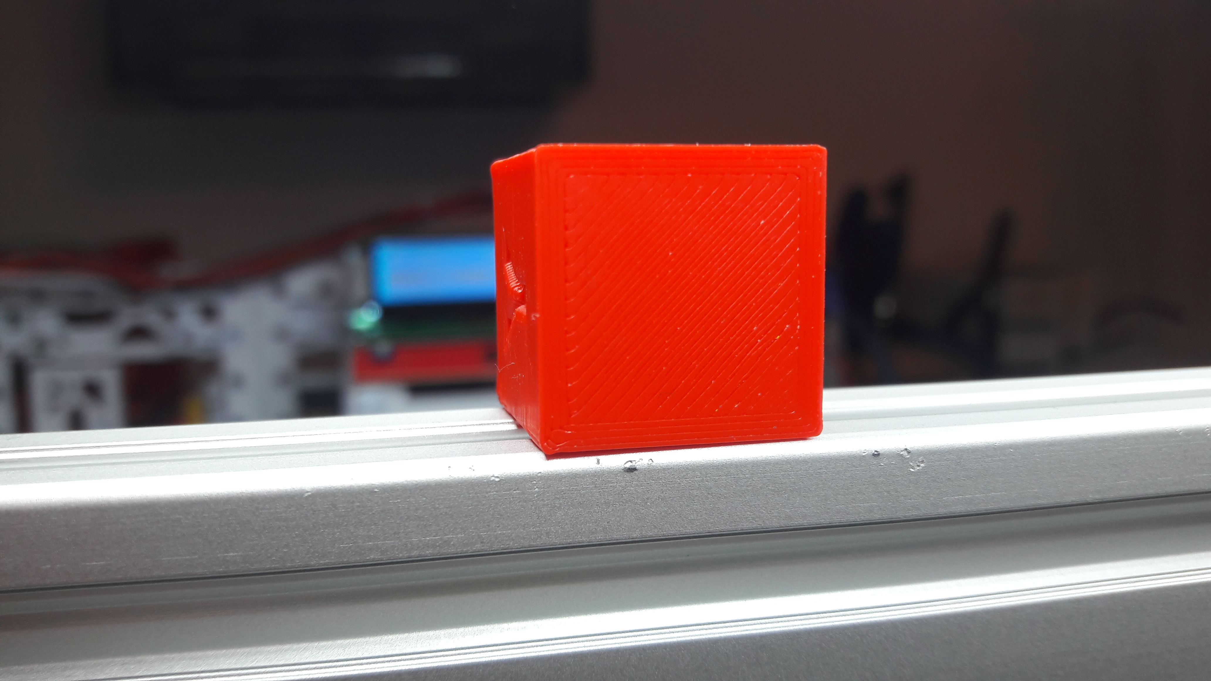
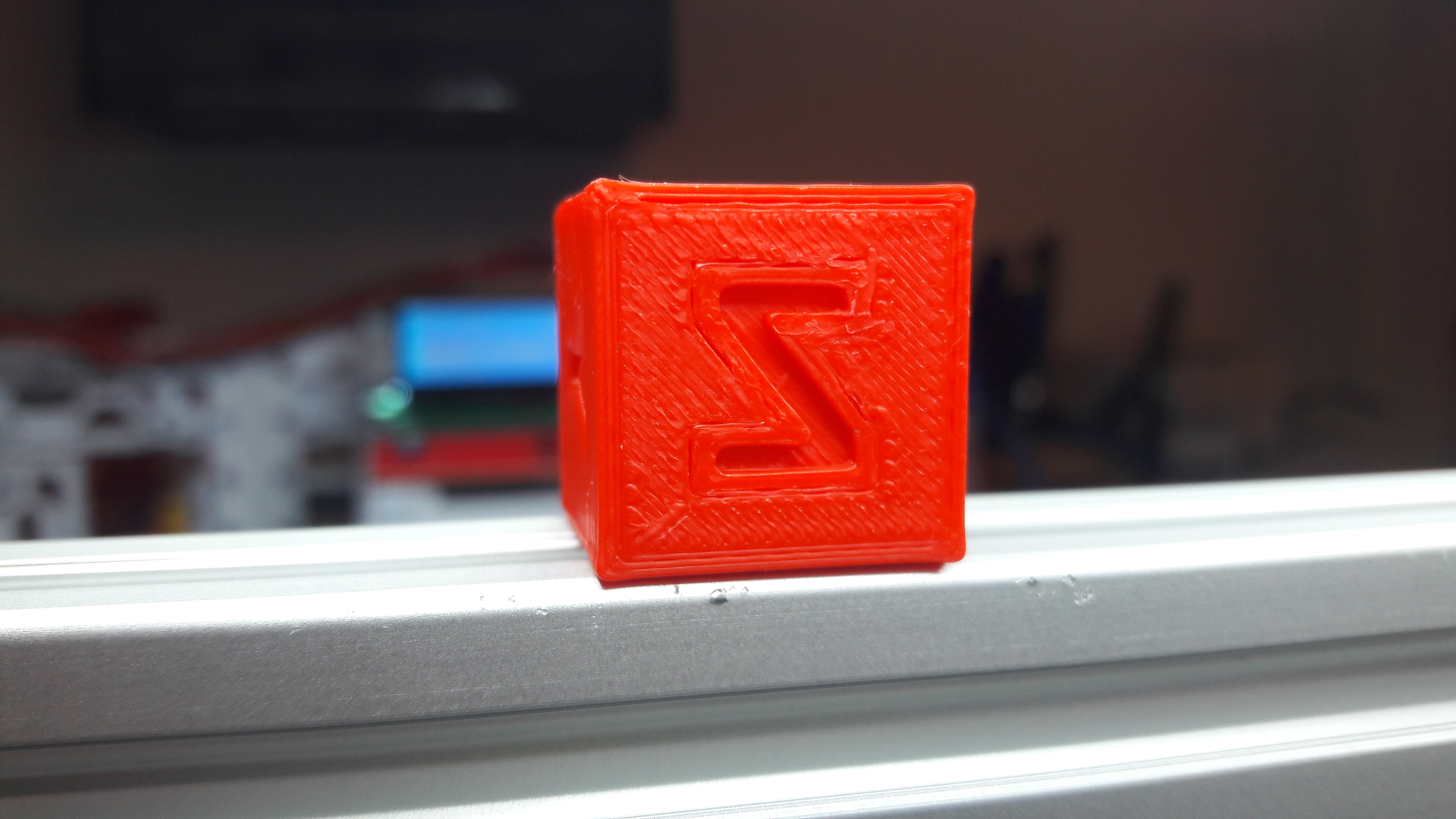
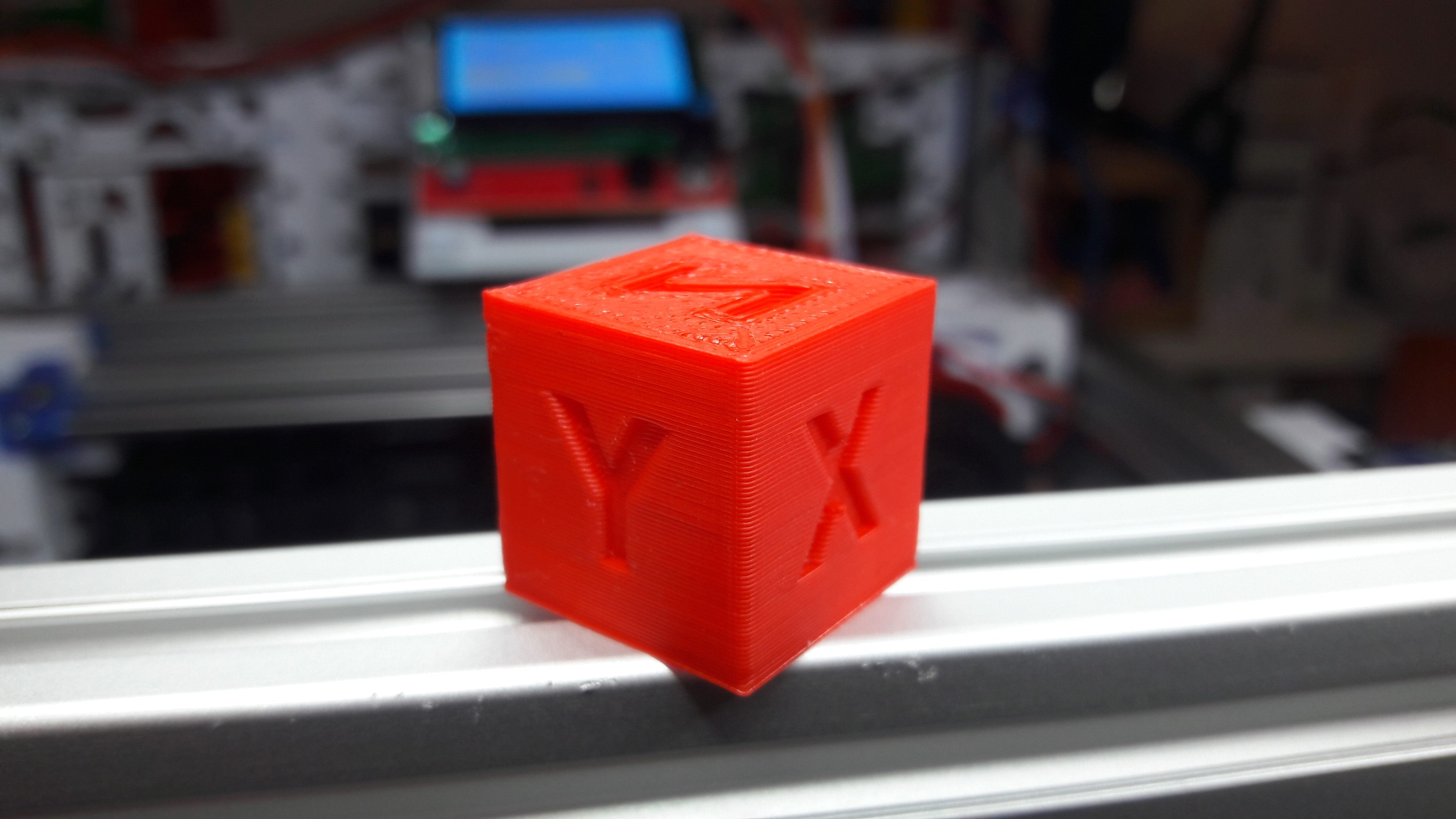
Here are some close ups of the finished cube:

Next Steps
The WeirdCube prints, and it prints unexpectedly well. I was very glad it worked so nicely. After all, I never designed and assembled a 3D printer before.
Is the project done? By far not. I still need to work on the cable management. The print head is not done yet. I wanted to integrate a bed leveling sensor (3D Touch) and also try out a direct drive extruder. The overall design of the print head also needs improvement. I want to see the nozzle when it's printing the first layer, but the fan duct is in the way. Last but not least I want to try to house it in at least a bit. The electronics on the back are exposed, which also need some form of cover to be protected a bit from dust and accidental damaging.
