Week of Weird Constructions 2
This week I concentrated on the Raspberry Pi Pico Rust Hardware Abstraction Layer. I looked into the cortex-m-rtic crate for Real-Time Interrupt-driven Concurrency, and also contributed more examples to the rp-pico - Board Support for the Raspberry Pi Pico.
RTIC and WS2812
While I was preparing the WS2812 Example last week for the Pico board, someone wondered if it was possible to use the ws2812-pio-rs crate by ithinuel in combination with cortex-m-rtic crate. And indeed, it was not.
The root of the problem was, that ws2812-pio-rs takes a CountDown timer, which
takes a reference to the system Timer. And then you want to store the Ws2812
instance eg. in Shared. However, the Timer instance is also owned by Shared,
so you can control alarms for timer driven tasks.
Self referential structures don't really work in Rust and are also a bad pattern.
So I decided to prepare a pull-request for the ws2812-pio-rs here:
ws2812-pio-rs Ws2812Direct Pull Request.
The change splits up the existing implementation and allow a Ws2812Direct variant, that
does not require to own a CountDown. This is roughly how the code looks now:
#[rtic::app(device = pico::hal::pac, peripherals = true)]
mod app {
    // ...
    use ws2812_pio::Ws2812Direct;

    #[shared]
    struct Shared {
        timer: Timer,
        alarm: hal::timer::Alarm0,
        led:   hal::gpio::Pin<hal::gpio::pin::bank0::Gpio25, hal::gpio::PushPullOutput>,
        ws:    Ws2812Direct<pico::hal::pac::PIO0, SM0, hal::gpio::pin::bank0::Gpio4>,
    }

    #[init]
    fn init(c: init::Context) -> (Shared, Local, init::Monotonics) {
        let mut resets = c.device.RESETS;
        let mut watchdog = Watchdog::new(c.device.WATCHDOG);
        let clocks = init_clocks_and_plls(
            // ...
        )
        .ok()
        .unwrap();

        let mut timer = Timer::new(c.device.TIMER, &mut resets);
        let mut alarm = timer.alarm_0().unwrap();
        // ...

        let (mut pio, sm0, _, _, _) = c.device.PIO0.split(&mut resets);
        let ws = Ws2812Direct::new(
            pins.gpio4.into_mode(),
            &mut pio,
            sm0,
            clocks.peripheral_clock.freq(),
        );

        // Shared now owns the Ws2812Direct instance and you can
        // use it from a timer task (see below).
        (Shared { timer, alarm, led, ws }, Local {}, init::Monotonics())
    }

    #[task(
        binds = TIMER_IRQ_0,
        priority = 1,
        shared = [timer, alarm, ws],
        local = [],
    )]
    fn timer_irq(mut c: timer_irq::Context) {
        let clr : RGB8 = (255, 0, 255).into();

        // Access the Shared data for the instance to the
        // Ws2812Direct driver instance:
        c.shared.ws.lock(|ws|
            ws.write([clr].iter().copied()).unwrap());

        // ...
    }
For a full example you can look at my rtic_ws2812_pio example.
SSD1306 Example
Next up I finally grabbed one of the SSD1306 OLED displays that I ordered many weeks ago:
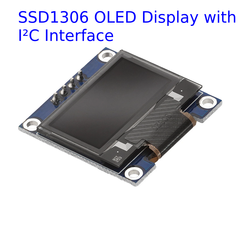
First I thought I would have to research and develop the I²C protocol implementation myself, but I was lucky and found a ssd1306 OLED driver crate which implemented what I needed!
So I connected up the display to my Raspberry Pi Pico (yea, still an ASCII art diagram, maybe at some point in future I will do more with KiCAD again):
                             VCC   SCL
                  /------------\    /----------\
                  |        GND  \  /  SDA      |
  _|USB|_         |    /-----\  |  |  /--------+--\
 |1  R 40|        |   /    __|__|__|__|___     |  |
 |2  P 39|        |  /    | ____________  |    |  |
 |3    38|- GND --+-/     | |Hello worl|  |    |  |
 |4  P 37|        |       | |Hello Rust|  |    |  |
 |5  I 36|-+3.3V -/       | |counter: 1|  |    |  |
 |6  C   |                | |          |  |    |  |
 |7  O   |                | """"""""""""  |    |  |
 |       |                 """""""""""""""     |  |
 |       |       (SSD1306 128x64 OLED Display) |  |
 .........                                     /  /
 |       |                                    /  /
 |     22|-GP17 I2C0 SCL---------------------/  /
 |20   21|-GP16 I2C0 SDA-----------------------/
  """""""
Symbols:
    - (+) crossing lines, not connected
    - (o) connected lines
So far so good, I also quickly researched how to format numbers in embedded Rust and came up with this (notice that I left it running for more than 11 hours to get up to 80000):
I wanted to explore more artistic stuff and took a simple drawing function I found on an old demo archive: flipcode - The Art of Demomaking - Per Pixel Control
// Adapted from The Art of Demomaking by Alex Champandard:
fn draw_grayscale_image(out: &mut [f32; 64 * 128]) {
    let sin = pico::hal::rom_data::float_funcs::fsin();
    let cos = pico::hal::rom_data::float_funcs::fcos();

    for x in 0..128 {
        for y in 0..64 {
            let xf = x as f32;
            let yf = y as f32;

            let sf = 0.2; // scale factor

            let r = 64.0
                + 63.0
                    * sin(xf / (sf * (37.0 + 15.0 * cos(yf / (sf * 74.0)))))
                    * cos(yf / (sf * (31.0 + 11.0 * sin(xf / (sf * 57.0)))));

            out[x + y * 128] = r;
        }
    }
}
And then made an animation over the threshold:
I also wrote an example for the rp-pico board in the rp-hal repository, which already was merged in:
If you search for a full piece of code for the animation above, it remained in my own private repository:
Bugfix rp-hal Alarm Schedule
While chatting with the nice folks on the #rp-rs:matrix.org channel,
Mathias noticed that there was a race condition in the current alarm implementation
for the Timers:
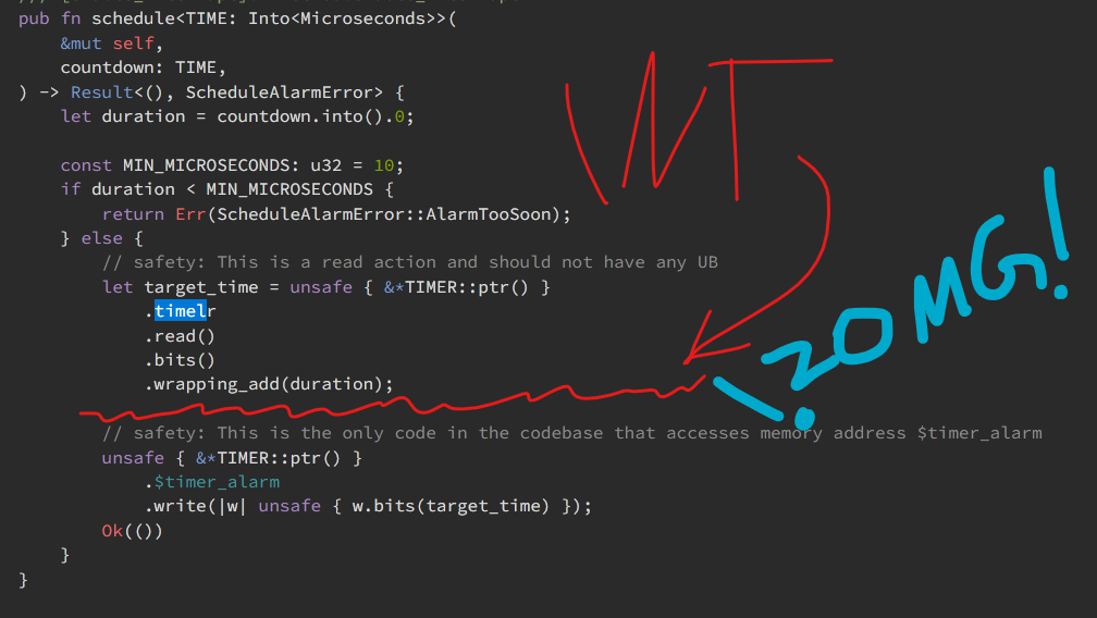
I quickly made a patch and submitted a PR to rp-hal:
Big thanks to VictorKoenders on GitHub for adding the Timer alarms methods in the first place!
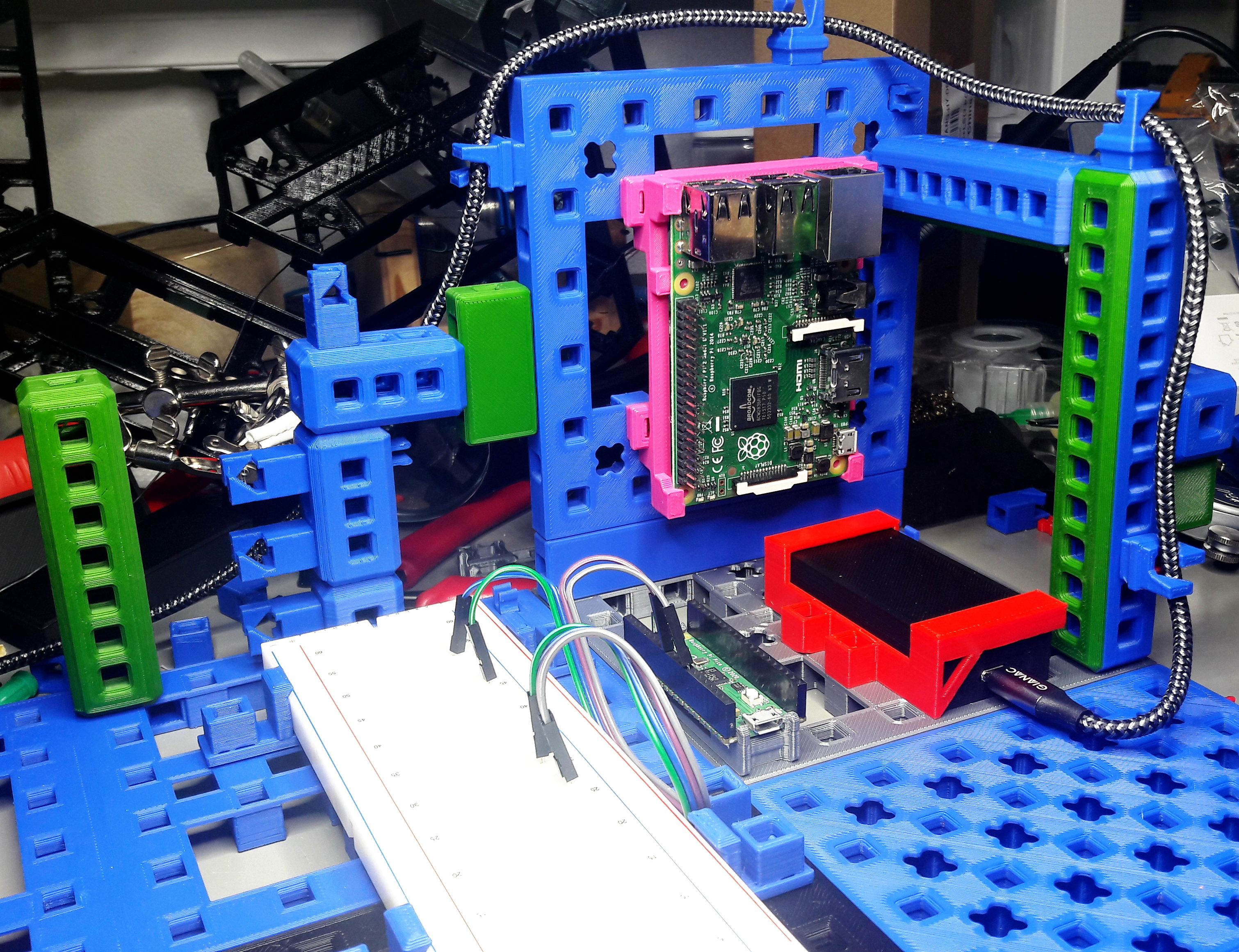
MakerGrid - 3D Printing For Modular Electronics Prototype Setups
Usually my test setups/prototypes/experiments don't fit on just one breadboard. They usually either span multiple breadboards (that are incompatible/don't fit) or are separate modules. So I came up with screwing things down into a piece of wood, which usually looks rather ugly and is not really modular or satisfying:

Last week I had an idea after watching a video about 3D Printing Professor's PrintABloks:
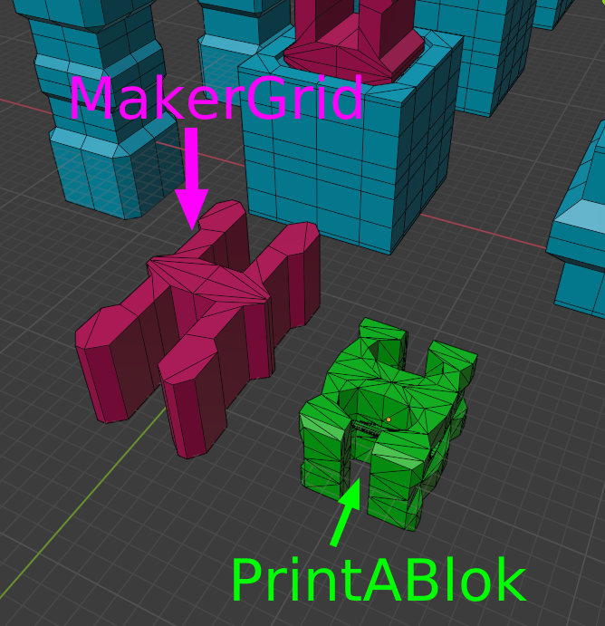
I wanted something similar, but with less directed towards toys, and more towards makers/electronics tinkerers like myself. And last Friday I came up with the 3D Printed MakerGrid! After a weekend full of printing and designing in Blender I had these prototypes:
After researching more, I also found that the PrintABlok system is rather finicky with the rather small clips as interconnection:
If you are interested, visit the project page:
